Cold and heat balanced ceramic valve

A ceramic valve and balanced technology, applied in the field of ceramic valves, can solve the problems of inconsistent industrial economic benefits, excessively increased manufacturing costs, and the combination of ceramic valves and faucets.

Active Publication Date: 2014-10-29
童炳荣
View PDF11 Cites 0 Cited by
  • Summary
  • Abstract
  • Description
  • Claims
  • Application Information

AI Technical Summary

Problems solved by technology

[0007] One point of view to be explained by enumerating the aforementioned conventional structures is: once the volume, specification, outer diameter or height of the valve body, and the position of the hot and cold water inlet holes of the ceramic valve are different from those of the general standard ceramic valve, it means that the ceramic valve is intended to be installed. The size of the valve slit and the location of the hot and cold water inlet channels of the installed faucet body must be changed accordingly. As a result, once the conventional ceramic valve needs to be equipped with a cold and hot balance valve structure, it cannot be compared with the existing one. There is a problem that regular standard ceramic valves and faucet products are used together; that is to say, if the industry wants to produce ceramic valve products with cold and hot balance valves, it is almost necessary to re-open the mold to manufacture a new ceramic valve. Manufacture of new faucet body valve slot and hot and cold water inlet flow channel type can make the ceramic valve meet the functional demands of cold, hot and temperature balance, so because too many process links must be used and changed, it will inevitably increase the manufacturing cost. Good industrial economic benefits

Method used


Image

  • Cold and heat balanced ceramic valve
  • Cold and heat balanced ceramic valve
  • Cold and heat balanced ceramic valve

Examples


Embodiment Construction

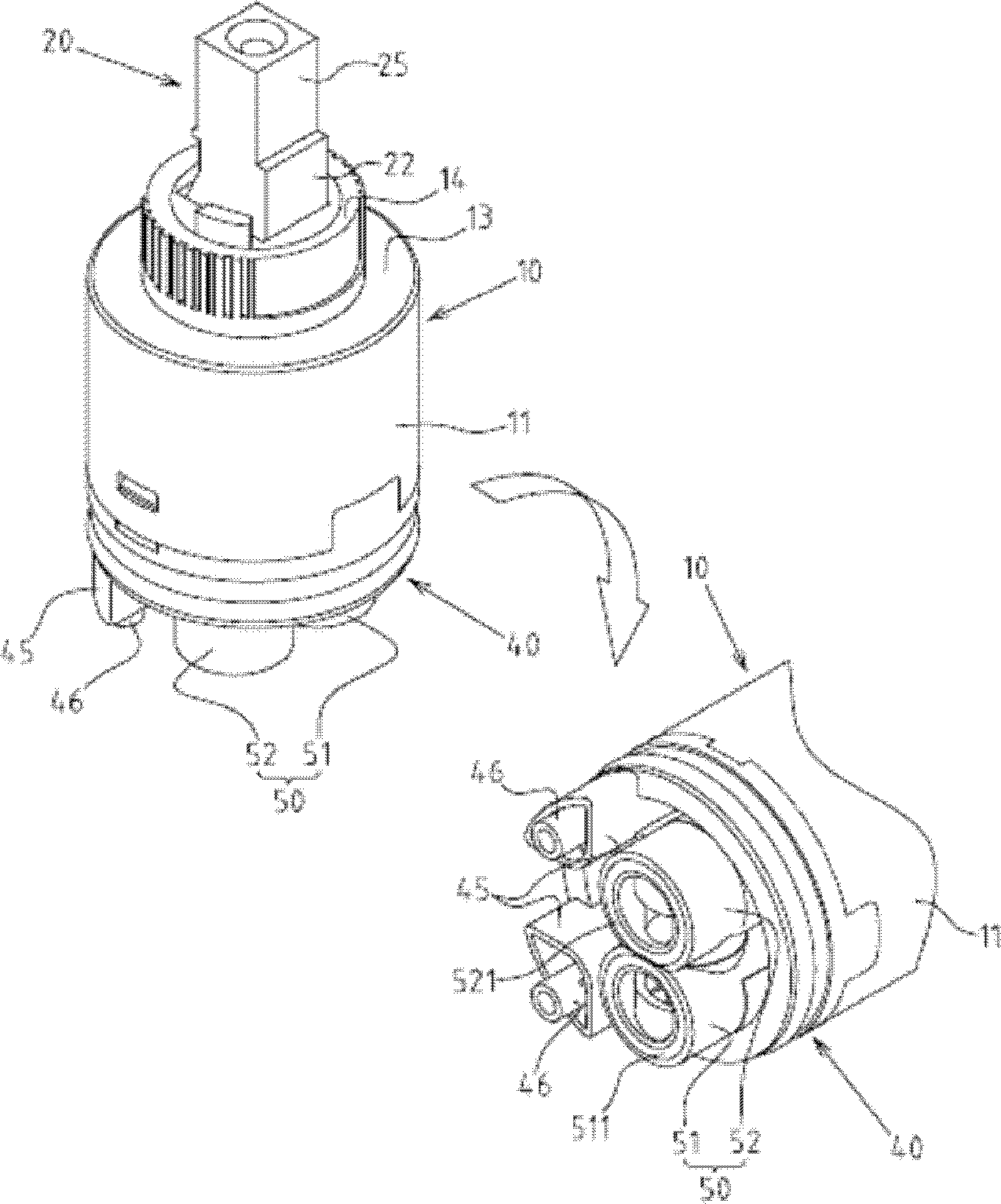
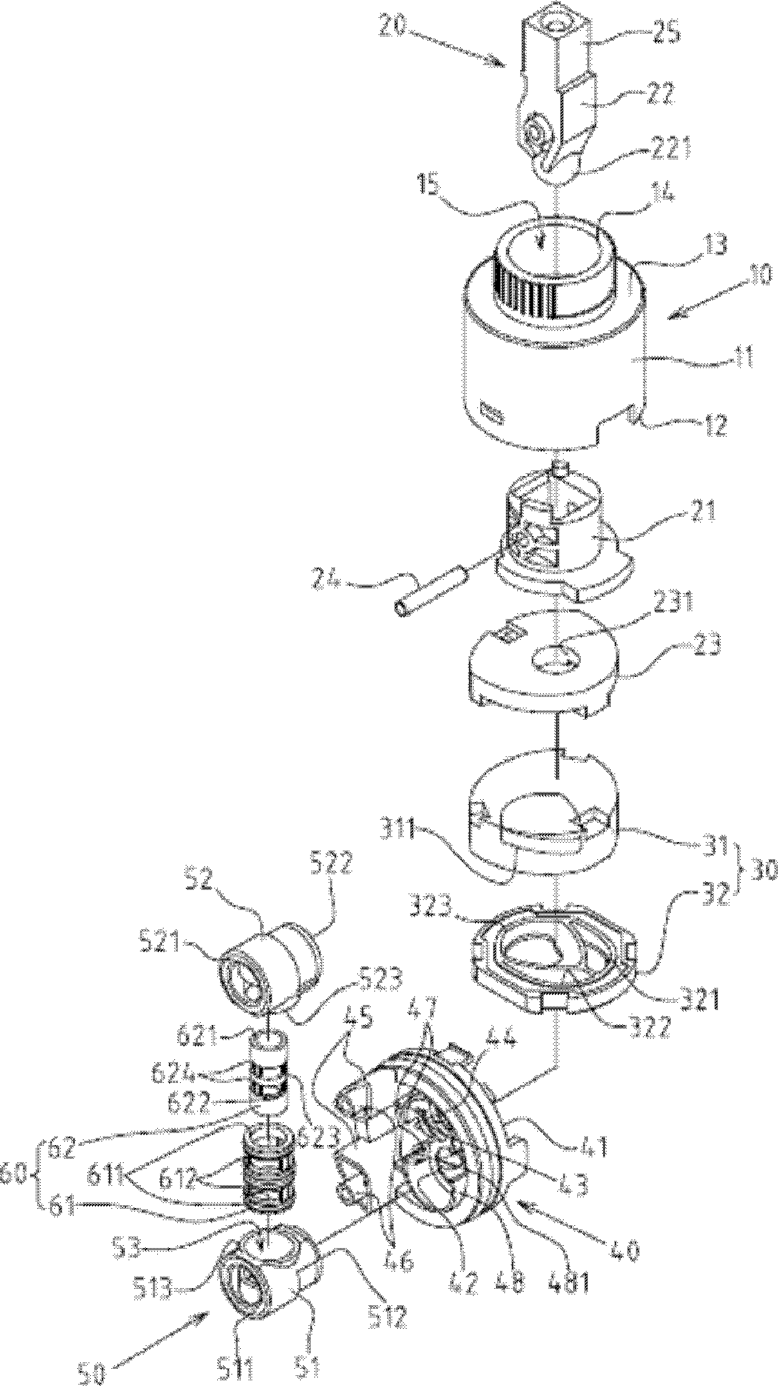
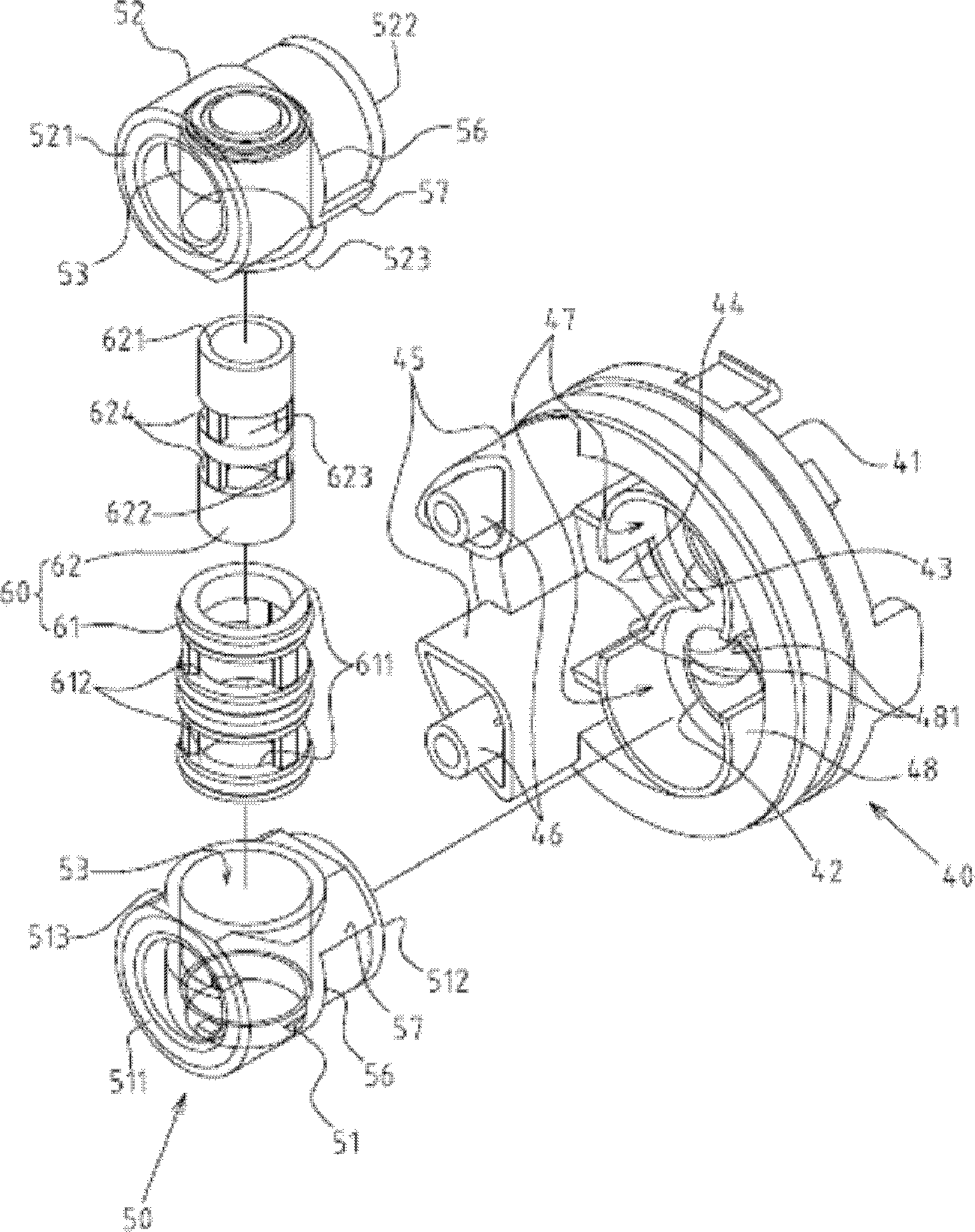
[0023] Such as figure 1 , 2 , 3, and 4 show the preferred embodiments of the cold and heat balanced ceramic valve of the present invention, but these embodiments are for illustration only, and are not limited by this structure in patent applications. The cold and heat balanced ceramic valve includes:

[0024] A standard valve housing 10 includes a peripheral wall 11, a bottom opening 12, a top end surface 13, a reduced diameter nozzle 14, and an internal storage space 15 are arranged on the top end surface 13, and wherein, the peripheral wall of the standard valve housing 10 11 The outer diameter size must be 40mm±1mm or 35mm±1mm in the standard specifications of ceramic valve products (as shown in D1 in Figure 4);

[0025] A water control member 20 includes a rotating seat 21, a lever 22 and a link plate 23, wherein the rotating seat 21 is rotatably assembled in the reduced-diameter nozzle 14 of the standard valve housing 10, and the lever 22 The middle section is pivotall...


PUM


Abstract

The invention discloses a cold and hot balancing ceramic valve which is characterized in that under the condition that the outer diameter and height of a valve casing and a high-leg base meet the existing system specification condition of a ceramic valve product, a water inlet pipe accommodating groove is arranged at the bottom ends of a cold water hole and a hot water hole of the high-leg base and used for arranging a combined water inlet pipe group arranged in inclined mode. The combined water inlet pipe group is formed by a cold water pipe body and a hot water pipe body. Adjacent sides of the hot water pipe body and the cold water pipe body are opposite and combined to form a balancing valve accommodating space inside the adjacent sides, and the balancing valve accommodating space is used for accommodating a cold and hot balancing valve construction member. A cold and hot balancing ceramic valve structure capable of being applied to the existing system ceramic valve specification generally is provided, manufacture cost of the cold and hot balancing ceramic valve is greatly reduced, a cold and hot balancing function is achieved, practicality advancement and better industrial economic benefit are achieved.

Description

technical field [0001] The invention relates to a ceramic valve with cold, hot and temperature balancing functions, in particular to a new type of cold and hot balanced ceramic valve which can be commonly used in the specifications of existing standard ceramic valves. Background technique [0002] Press, in view of the problems that the traditional dual-temperature ceramic valve is easy to accidentally turn the faucet by hand during the use process, causing instant overheating and scalding of the water temperature, and unstable changes in cold and hot water pressure, which make it difficult to control the water temperature, so some related industries developed a valve. There is an improved ceramic valve structure of a cold and hot balance valve inside the shell. [0003] Although there are quite a lot of ceramic valve products equipped with cooling and heating balance valves and related technology patents on the market, there are still some problems and shortcomings that can...

Claims


Application Information

Patent Timeline
Patent Type & Authority Patents(China)
IPC IPC(8): F16K11/20
Inventor 童炳荣
Owner 童炳荣
Why Eureka
Try Eureka