
Method and device for detecting solid fraction and final stage of solidification of continuously cast slab

A technology of solidification end and detection method, which is applied in measurement devices, flow characteristics, instruments, etc., can solve the problems of poor accuracy, inability to detect the solid phase ratio of continuous casting slabs, and inability to measure continuously for a long time, so as to improve detection accuracy, The effect of convenient and quick repeated online detection

Inactive Publication Date: 2013-04-17
中冶赛迪电气技术有限公司
View PDF9 Cites 13 Cited by
  • Summary
  • Abstract
  • Description
  • Claims
  • Application Information

AI Technical Summary

Problems solved by technology

Since the slab pressure needs to be evenly distributed to each casting roll in this type of method, although it can roughly determine the position of the solidification end of the slab, it cannot detect the solid phase ratio of the continuous casting slab
[0008] The Chinese patent application with the publication number CN102500747A discloses a technical solution for detecting the solidification end of continuous casting slabs by using electromagnetic ultrasonic technology. There are many problems such as the range of lift-off and the inability to measure continuously for a long time stably. There is no report on the successful application of the technology of using electromagnetic ultrasonic technology to detect the solidification end of continuous casting slabs.

Method used


Image

  • Method and device for detecting solid fraction and final stage of solidification of continuously cast slab
  • Method and device for detecting solid fraction and final stage of solidification of continuously cast slab
  • Method and device for detecting solid fraction and final stage of solidification of continuously cast slab

Examples


Embodiment Construction

[0044] The preferred embodiments of the present invention will be described in detail below with reference to the accompanying drawings.

[0045] Firstly, the specific implementation of the method for detecting the solid phase ratio and solidification end of the continuous casting slab of the present invention will be described in detail.

[0046] The detection method of the continuous casting slab solid phase ratio and solidification end of the present embodiment comprises the following steps:

[0047] 1) Vibration excitation is applied to the continuous casting billet 1, and the continuous casting billet 1 undergoes elastic deformation under the action of the vibration excitation;

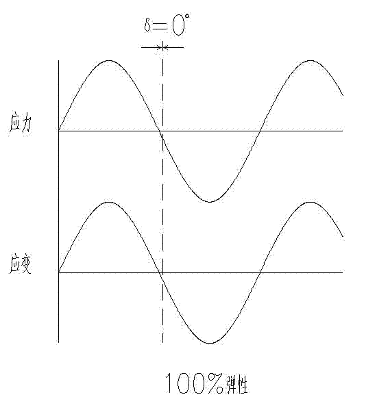
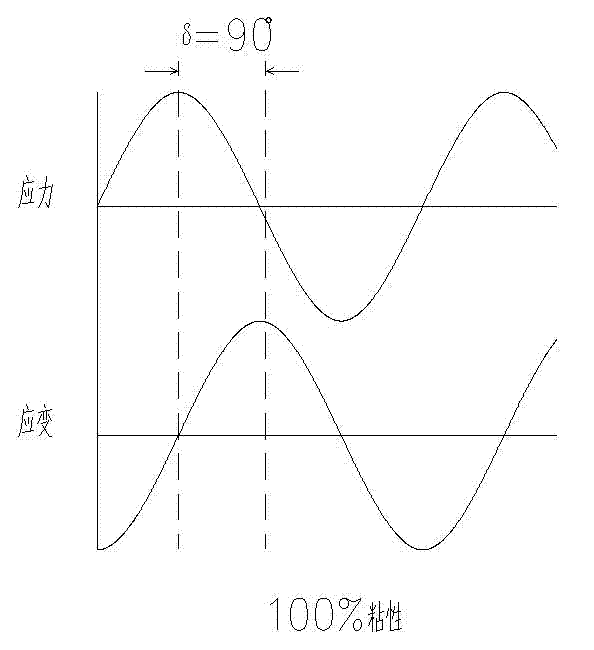
[0048] 2) After the continuous casting slab 1 resonates with the oscillation excitation, measure the strain of the elastic deformation of the continuous casting slab 1, the stress load applied to the continuous casting slab 1 by the oscillation excitation, and the stress / Strain phase difference...


PUM


Abstract

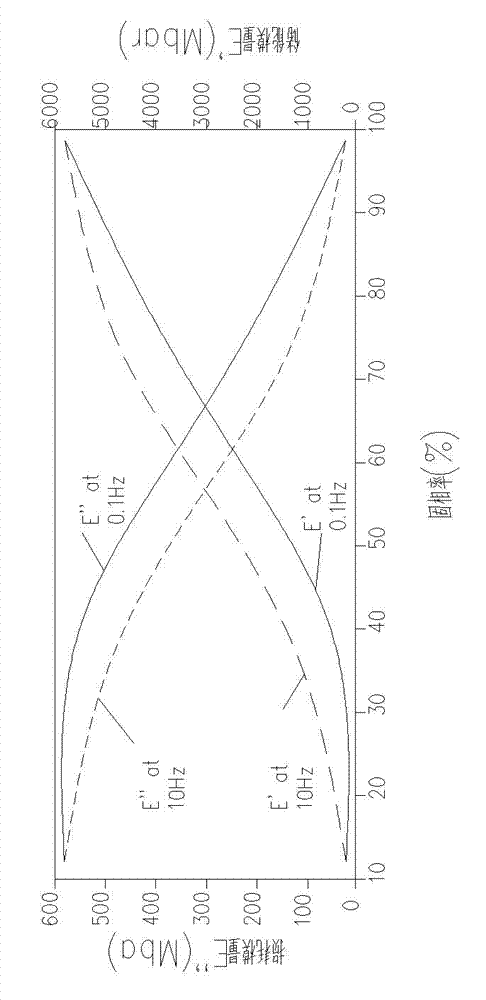
The invention discloses a method for detecting solid fraction and final stage of solidification of a continuously cast slab. The method comprises the following steps of: (1) applying oscillation excitation to the continuously cast slab, so that the continuously cast slab generates elastic deformation under oscillation excitation; (2) measuring the strain of elastic deformation of the continuously cast slab, the stress loads applied on the continuously cast slab by oscillation excitation, and the stress / strain phase difference of elastic deformation of the continuously cast slab with oscillation excitation after the continuously cast slab generates resonance to oscillation excitation; (3) calculating dynamic modulus of the continuously cast slab; and (4) obtaining the solid fraction and final stage of solidification of the continuously cast slab according to a solid fraction and dynamic modulus characteristic curve of the continuously cast slab. The invention also discloses a device for detecting solid fraction and final stage of solidification of a continuously cast slab. The method and the device provided by the invention can conduct nondestructive online measurement on the continuously cast slab, and can improve the solid fraction detection accuracy as well as the location accuracy of final stage of solidification of the continuously cast slab.

Description

technical field [0001] The invention belongs to the technical field of metal casting, and in particular relates to a detection method and a detection device for the solid phase ratio and solidification end of a continuous casting slab. Background technique [0002] In the field of slab continuous casting technology, with the continuous development of technology and the increasingly intensified market competition in the iron and steel industry, the quality of slabs has gradually become a key limiting factor in continuous casting production, and has been paid more and more attention by users and manufacturers, especially When producing high-quality steel and special-purpose steel, higher requirements are put forward for the quality of continuous casting slabs. [0003] In the continuous casting technology, the molten steel is cooled inside the mold and forms a solidified slab shell with a certain thickness. After leaving the mold, the inside of the slab is still in a liquid st...

Claims


Application Information

Patent Timeline
Patent Type & Authority Applications(China)
IPC IPC(8): G01N11/00B22D11/16
Inventor 何新军龙灏陈将彭晓华曾珊林晓泽
Owner 中冶赛迪电气技术有限公司
Learn More