3 * 3 free-space optical router

A free space and router technology, which is applied in the coupling of optical waveguide, digital transmission system, data exchange network, etc., can solve the problems that optical signals cannot be realized, routing control cannot be realized, etc., and achieve fast response speed, simple structure and easy installation Effect

Active Publication Date: 2013-04-17
SHANGHAI INST OF OPTICS & FINE MECHANICS CHINESE ACAD OF SCI
View PDF4 Cites 1 Cited by
  • Summary
  • Abstract
  • Description
  • Claims
  • Application Information

AI Technical Summary

Problems solved by technology

However, it cannot realize the exchange of optical signals between input-input ports and output-output ports, that is, it cannot realize complete routing control functions

Method used


Image

  • 3 * 3 free-space optical router
  • 3 * 3 free-space optical router
  • 3 * 3 free-space optical router

Examples


Embodiment Construction

[0027] The 3×3 free-space optical router of the present invention will be further described below in conjunction with the accompanying drawings, but this should not limit the protection scope of the present invention.

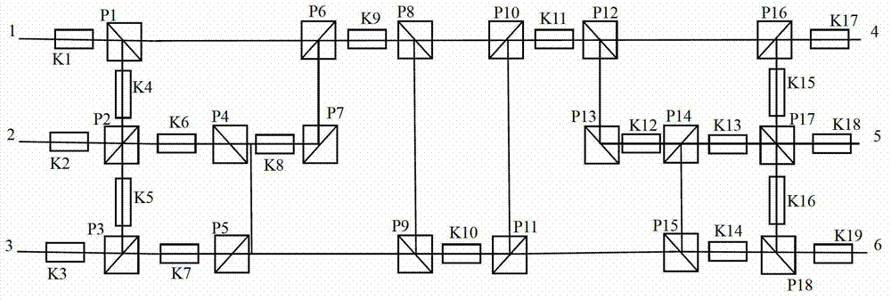
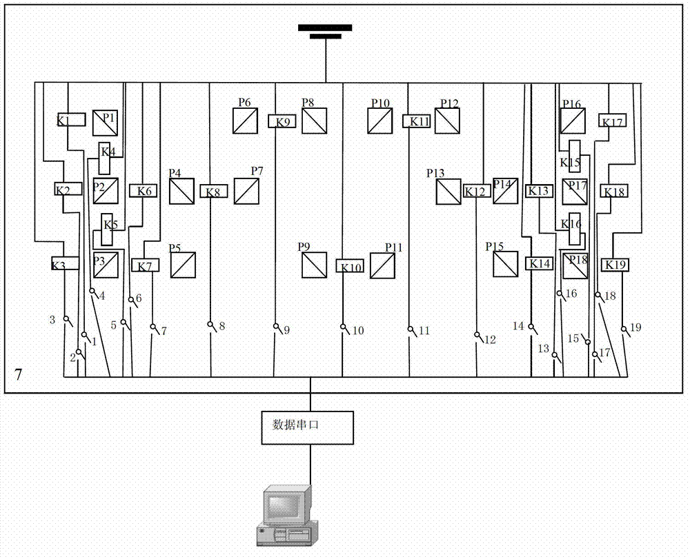
[0028] see figure 1 with figure 2 , figure 1 It is a schematic diagram of the optical path structure of the 3×3 free space optical router of the present invention, figure 2 It is a schematic diagram of the electrical structure of the 3×3 free-space optical router of the present invention. It can be seen from the figure that the 3×3 free-space optical router of the present invention consists of 19 optical switches with the same structure including 6 beam channels, and 18 optical switches with the same structure. The polarizing beam splitter has 19 electric switches with the same structure, a circuit control board 7, a power supply and a computer, and the positional relationship of the above-mentioned components is as follows:

[0029] The first beam channel...


PUM


Abstract

The invention relates to a 3*3 free-space optical router, which comprises six beam channels, eighteen polarization beam splitters, nineteen optical switches and nineteen electrical switches which are integrated on one circuit control board, wherein one end of each optical switch is connected with a power supply, and the other end of each optical switch is connected with the other end of the power supply through the corresponding electrical switch; and the control end of each electrical switch is connected with the output end of a computer through a data line. The computer can realize non-blocking connection between any two channels of the six channels by controlling the polarization state of signal light. The router provided by the invention has the advantages of simple structure, fast response, non-blocking connection, high-speed parallel, high capacity and the like, and is suitable for various optical interconnection networks.

Description

technical field [0001] The invention relates to an optical router, in particular to a 3*3 free-space optical router, which can quickly realize the simultaneous non-blocking connection between any two channels in six channels. It is suitable for various optical interconnection networks and space laser communication. Background technique [0002] Large-bandwidth optical interconnection and optical switching technology with fast switching capability has great application prospects in computer and optical communication systems, so it has become the frontier and hot spot of information optics research and development. The optical interconnection network is derived and developed from the electronic interconnection network, and the topology of the network is realized by the optical interconnection and the optical switch array. Due to the "bottleneck" of electronic circuit bandwidth, which limits the throughput of network nodes, optical switches are crucial to the functional realiz...

Claims


Application Information

Patent Timeline
Patent Type & Authority Applications(China)
IPC IPC(8): G02B6/35G02B6/27H04L12/771H04L45/60
Inventor 侯培培孙建锋职亚楠王利娟刘立人
Owner SHANGHAI INST OF OPTICS & FINE MECHANICS CHINESE ACAD OF SCI
Why Eureka
Try Eureka