
Magnetic valve type controllable electric reactor

A reactor and magnetic valve type technology, applied in the field of magnetic valve type controllable reactors, can solve the problems of poor reactor adjustment linearity, difficulty in reducing manufacturing costs, and difficult assembly, etc., to achieve good adjustment linearity and balance Smoothness and ease of assembly

Inactive Publication Date: 2013-04-17
ANHUI ONESKY ELECTRIC TECH
View PDF8 Cites 1 Cited by
  • Summary
  • Abstract
  • Description
  • Claims
  • Application Information

AI Technical Summary

Problems solved by technology

However, this magnetic valve type controllable reactor has many deficiencies. First, due to the multi-step ladder shape of the magnetic valve, it can only be saturated in sections, resulting in poor adjustment linearity of the reactor and poor output characteristics. It is not good; secondly, when the iron core with symmetrical multi-level stepped shape is laminated with silicon steel sheets, its assembly is extremely difficult, which is labor-intensive and time-consuming, making it difficult to reduce the manufacturing cost

Method used


Image

  • Magnetic valve type controllable electric reactor

Examples


Embodiment Construction

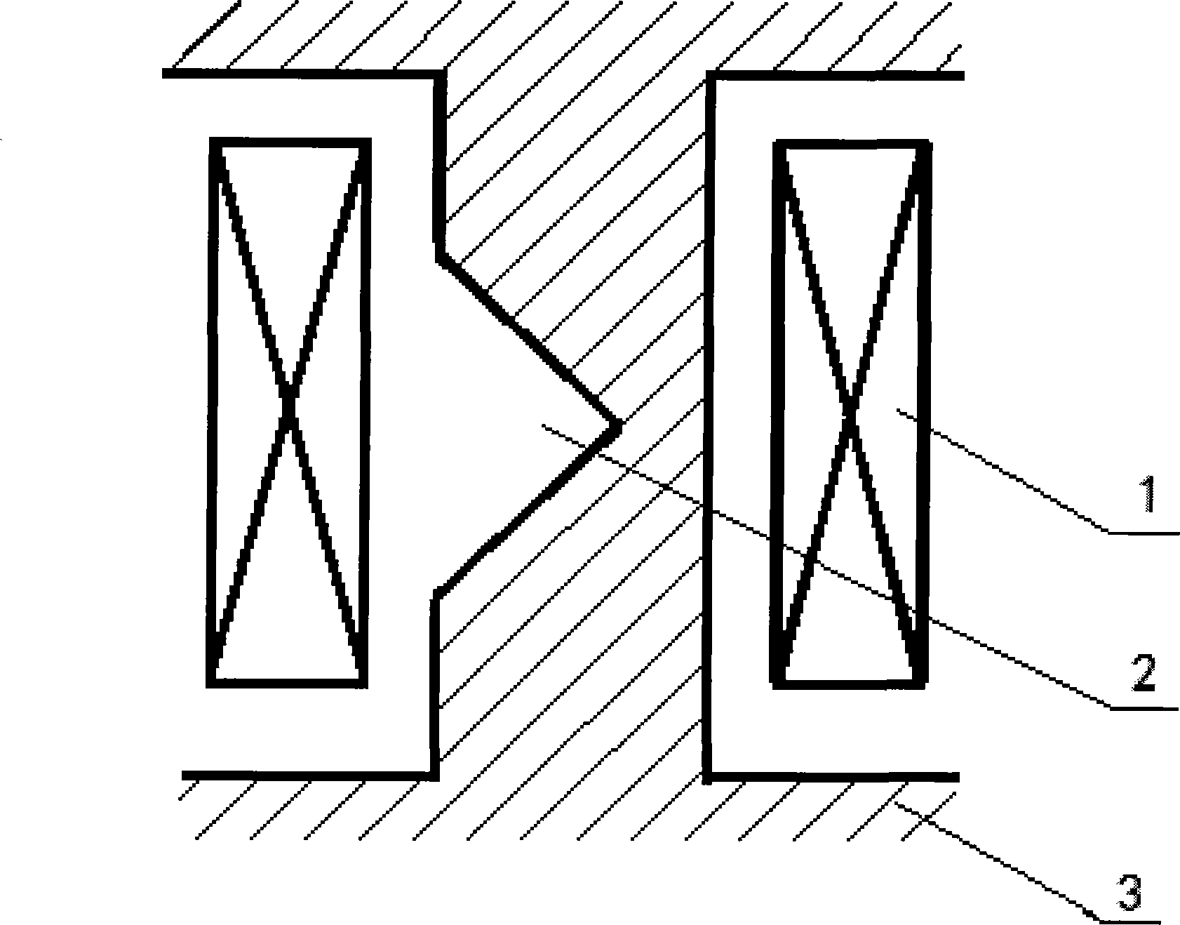
[0011] see figure 1 , the composition of the magnetic valve type controllable reactor is as follows: the iron core 3 made of silicon steel sheets has a gap of the magnetic valve 2, and the cross section of the iron core 3 at the gap of the magnetic valve 2 is V-shaped; wherein, the V-shaped magnetic valve 2 The angle between the two slopes of the notch is 90 (can be 70-150) degrees, and the notch of the V-shaped magnetic valve 2 is located on one side of the iron core 3 . The iron core 3 is externally provided with a coil 1 matched therewith.

[0012] When in use, by adjusting the current in the coil 1, the reactor output with uniform saturation of the iron core can be obtained, and the required linearly changing reactor output can be obtained.

[0013] Apparently, those skilled in the art can make various changes and modifications to the magnetic valve type controllable reactor of the present invention without departing from the spirit and scope of the present invention. Th...


PUM


Abstract

The invention discloses a magnetic valve type controllable electric reactor. The magnetic valve type controllable electric reactor consists of an iron core (3) formed by stacking silicon steel sheets and provided with a magnetic valve (2) gap and a coil (1) matched with the iron core (3). Especially, a cross section at the position of the magnetic valve (2) gap of the iron core (3) is V-shaped. An included angle formed by two oblique faces of the V-shaped magnetic valve (2) gap is 70-150 degrees, and the V-shaped magnetic valve (2) gap is located on one side of the iron core (3). The magnetic valve type controllable electric reactor is very good in linearity degree and excellent in output characteristics, has the advantage that the iron core (3) provided with the V-shaped magnetic valve (2) gap is formed by assembling and stacking the V-shaped gapped silicon steel sheets, and can be widely used for controlling of voltage and reactive power flow of high-voltage and ultra-high-voltage power grids, improvement of system stability, increasing of transmission power, limitation of power frequency and switching overvoltage of the ultra-high-voltage power grids, compensation (arc extinction) of one-phase grounding current, harmonic suppression of large-power rectifying systems and other occasions.

Description

technical field [0001] The invention relates to a reactor, in particular to a magnetic valve type controllable reactor. Background technique [0002] The magnetic valve controllable reactor is an important part of voltage control and reactive power compensation in the power system, and has received extensive attention in recent years; its application prospects are very broad, mainly used in the control of voltage and reactive power flow in high-voltage and ultra-high-voltage power grids , Improve the stability of the system and increase the transmission power, limit the power frequency and operating overvoltage of the ultra-high voltage power grid, single-phase ground current compensation (arc suppression), harmonic suppression of high-power rectification systems, etc. At present, the magnetic valve in the magnetic valve type controllable reactor adopts a symmetrical multi-level ladder structure, that is, the shape of the magnetic valve on the iron core is a symmetrical mult...

Claims


Application Information

Patent Timeline
Patent Type & Authority Applications(China)
IPC IPC(8): H01F27/24H02J3/18
CPCY02E40/30
Inventor 芮骏洪新春
Owner ANHUI ONESKY ELECTRIC TECH
Learn More