Digital pulse width modulator based on digital delayed-locked loop (DLL)
A digital pulse width modulation, delay phase locked loop technology, applied in the direction of automatic power control, electrical components, etc., can solve the problem of large area, and achieve the effect of simple circuit structure, reduced area and cost saving
- Summary
- Abstract
- Description
- Claims
- Application Information
AI Technical Summary
Problems solved by technology
Method used
Image
Examples
Embodiment Construction
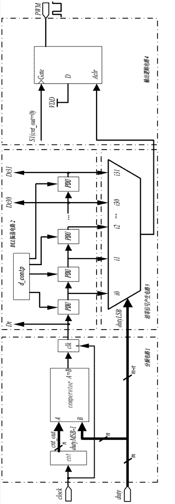
[0026] see Figure 4 , the present invention is based on the digital pulse width modulator of digital delay locked loop, comprises frequency division circuit 1, DLL oscillation ring circuit 2, reset signal generation circuit 3 and PWM output logic circuit 4, and prior art also includes these 4 parts.
[0027] The frequency division circuit 1 includes a counter 11 and a comparator 12, the clock signal input end of the counter 11 is connected with the system clock, the reset signal input end of the counter 11 is connected with the system reset signal, and the output of the counter 11 is connected with an input end of the comparator 12 , the other input terminal of the comparator 12 is grounded;
[0028] Clearing signal generation circuit 3 comprises comparator 31, selector 32 and a two-input AND gate 33, and an input end of comparator 31 is connected the output of counter 11 in frequency division circuit 1, and the other input end of comparator 31 is connected input The high nM...
PUM
 Abstract
Description
Claims
Application Information
 - R&D
- Intellectual Property
- Life Sciences
- Materials
- Tech Scout
- Unparalleled Data Quality
- Higher Quality Content
- 60% Fewer Hallucinations
Browse by: Latest US Patents, China's latest patents, Technical Efficacy Thesaurus, Application Domain, Technology Topic, Popular Technical Reports.
© 2025 PatSnap. All rights reserved.Legal|Privacy policy|Modern Slavery Act Transparency Statement|Sitemap|About US| Contact US: help@patsnap.com


