
Multi-stage pulse combustion control system and method

A technology of pulse combustion and control method, which is applied in the direction of combustion method, combustion control, and fuel supply adjustment, etc., can solve the problems of limited adjustment ratio, insufficient fuel combustion, uneven heating of workpieces, etc., to improve product quality and adjust linearity. The effect of good temperature and smooth combustion process

Active Publication Date: 2017-11-10
DALIAN UNIV
View PDF7 Cites 0 Cited by
  • Summary
  • Abstract
  • Description
  • Claims
  • Application Information

AI Technical Summary

Problems solved by technology

With this combustion control method, in actual production, the strong heat supply under the high fire state in the temperature control area is likely to cause local overheating of the workpiece, which makes the workpiece heated unevenly, that is, the output power of the burner is large in the high fire state, and the high fire output state is fixed. , during the heating process, the surface of the workpiece near the burner will heat up rapidly, causing the internal temperature difference of the workpiece to increase rapidly in a short time, affecting the heat treatment quality of the product; especially for some industrial furnaces, the temperature measurement point is set on the side of the furnace, and the burner The burning state of the fire will seriously interfere with the temperature detection of the adjacent temperature control area
In the continuous combustion mode, the output power of the burner can be adjusted, but the adjustment ratio is limited, especially in the low-load combustion control process of the kiln, it is easy to cause insufficient fuel combustion, poor air flow, and uneven distribution of temperature field in the furnace.

Method used


Image

  • Multi-stage pulse combustion control system and method
  • Multi-stage pulse combustion control system and method
  • Multi-stage pulse combustion control system and method

Examples


Embodiment 1

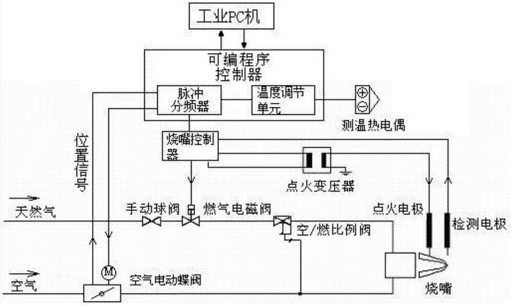
[0032] On the one hand, the present invention provides a multi-stage pulse combustion control system, including: temperature measuring thermocouple, programmable controller, burner controller, air electric butterfly valve, gas solenoid valve, air / fuel proportional valve, ignition transformer , burner; the programmable controller is respectively connected with the temperature measuring thermocouple, the input end of the burner controller, and the air electric butterfly valve on the air pipeline, and the output end of the described burner controller is respectively connected with the gas on the gas pipeline. The solenoid valve, ignition transformer, and burner are connected. The burner is connected with the burner controller through the detection electrode. The burner is connected with the ignition transformer through the ignition electrode. The air / fuel ratio valve is connected with the air electric butterfly valve. , Gas solenoid valve and burner are connected.

[0033] The pr...

Embodiment 2

[0040] On the one hand, the present invention provides a multi-stage pulse combustion control system, including: temperature measuring thermocouple, programmable controller, burner controller, air electric butterfly valve, gas solenoid valve, air / fuel proportional valve, ignition transformer , burner, industrial PC; the programmable controller is respectively connected with the temperature measuring thermocouple, the input end of the burner controller, and the air electric butterfly valve on the air pipeline, and the output end of the burner controller is respectively connected with the gas The gas solenoid valve on the pipeline, the ignition transformer, and the burner are connected. The burner is connected to the burner controller through the detection electrode. The burner is connected to the ignition transformer through the ignition electrode. The air / fuel ratio valve is respectively It is connected with air electric butterfly valve, gas solenoid valve and burner, and the p...

Embodiment 3

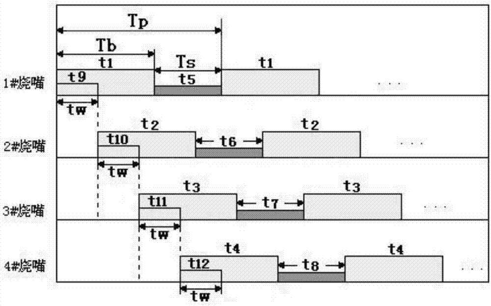
[0060] This embodiment is used as an example of the pulse frequency division method of the pulse frequency divider in Embodiment 2, please refer to figure 2 :

[0061] Taking the multi-segment pulse frequency division process of four burners in a certain temperature control section of a kiln as an example, the working process is clarified. T p , T b , T s They are the pulse combustion cycle, the burner high fire working cycle, and the burner low fire working cycle; the four burners are delayed in sequence according to a certain time, t w Delay the start time for each burner, that is, the delay time of the current start burner relative to the previous burner. T p , T b , T s ,t w Adjustable by industrial PC, t 1 -t 4 It is a timer used to control the fire of four burners, and the timing time is T b ;t 5 -t 8 In order to control the four burner small fire working timers, the timing time T s ;t 9 -t 12 In order to control the delay start timer of each burner, the...


PUM


Abstract

The invention discloses a multi-fragment pulse combustion control system and method. The multi-fragment pulse combustion control system comprises a temperature thermocouple, a programmable controller, a burner controller, an air electric butterfly valve, a fuel gas solenoid valve, a ratio valve of air to fuel, an ignition transformer and a burner, wherein the programmable controller is separately connected with the temperature thermocouple, the input end of the burner controller and the air electric butterfly valve; the output end of the burner controller is separately connected with the fuel gas solenoid valve, the ignition transformer and the burner; the burner is connected with the ignition transformer through an ignition electrode; and the ratio valve of air to fuel is separately connected with the air electric butterfly valve, the fuel gas solenoid valve and the burner through pipelines. The multi-fragment pulse combustion control system has the advantages that the furnace temperature is more uniform in distribution; the temperature control precision is high; the adjustment linear ratio is large; the design cost is low; and the like.

Description

technical field [0001] The invention belongs to the technical field of metallurgical combustion, and in particular relates to a multi-stage pulse combustion control system and method. Background technique [0002] Pulse combustion is a combustion control technology widely used in industrial furnaces. The main technical characteristics of pulse combustion currently used in the field are as follows: the burner usually works in two states, one is the state of high fire or full load combustion, that is, according to the process It is required to adjust the output power of the burner, the mixing ratio of fuel and air, and the speed of flame injection to the best output state at one time; the other is the state of low fire or flameout. During the pulse combustion process, the temperature adjustment is realized by adjusting the working cycle and time ratio of the large and small fires of each burner. [0003] When the temperature needs to be raised, the working time of the burner ...

Claims


Application Information

Patent Timeline
Patent Type & Authority Patents(China)
IPC IPC(8): F23N1/02
CPCF23N1/025
Inventor 胡玲艳
Owner DALIAN UNIV
Learn More