Method for precisely positioning fault of optical cable by utilizing rayleigh scattering and coherent optical time domain reflection technology

A technology of Rayleigh scattering and time domain reflection, applied in electromagnetic wave transmission systems, electrical components, transmission systems, etc., can solve the problems of long time, economic losses, and a large number of maintenance personnel, so as to improve maintenance efficiency and reduce maintenance costs. , the effect of shortened time

Inactive Publication Date: 2013-04-17
GUILIN G LINK TECH
View PDF0 Cites 33 Cited by
  • Summary
  • Abstract
  • Description
  • Claims
  • Application Information

AI Technical Summary

Problems solved by technology

[0004] 1. The deviation of the position accuracy of the fault point of the optical cable measured by the OTDR measurement curve is too large, the general error is 40-50 meters, and the maximum error can reach more than 100 meters
[0005] 2. It needs to be manually eliminated gradually, and may also need to implement long-distance line excavation and other work, which takes too long, seriously affects the normal recovery of communication, and causes serious economic losses
[0006] 3. A large number of maintenance personnel are required, which increases the cost of operation and maintenance

Method used


Image

  • Method for precisely positioning fault of optical cable by utilizing rayleigh scattering and coherent optical time domain reflection technology
  • Method for precisely positioning fault of optical cable by utilizing rayleigh scattering and coherent optical time domain reflection technology
  • Method for precisely positioning fault of optical cable by utilizing rayleigh scattering and coherent optical time domain reflection technology

Examples


Embodiment Construction

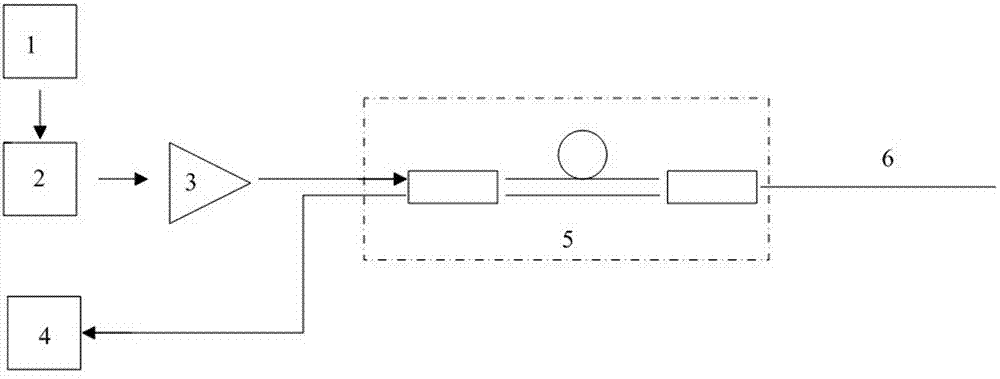
[0022] refer to figure 1 , the Rayleigh scattering and coherent optical time domain reflectometer of the present invention is formed by sequentially connecting a pulse generator 1, a laser 2 and an optical amplifier 3, and the optical amplifier 3 injects a laser signal into an interferometer 5 and an optical cable 6 based on the principle of a Sagnac ring, and the optical The receiver 4 receives the information of each point of the optical cable carried by the Rayleigh scattered light.

[0023] A method for accurately locating an optical cable fault using Rayleigh scattering and coherent optical time domain reflectometry, comprising the following steps:

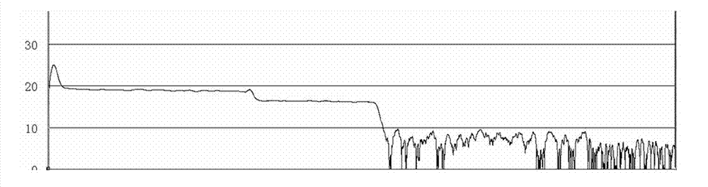
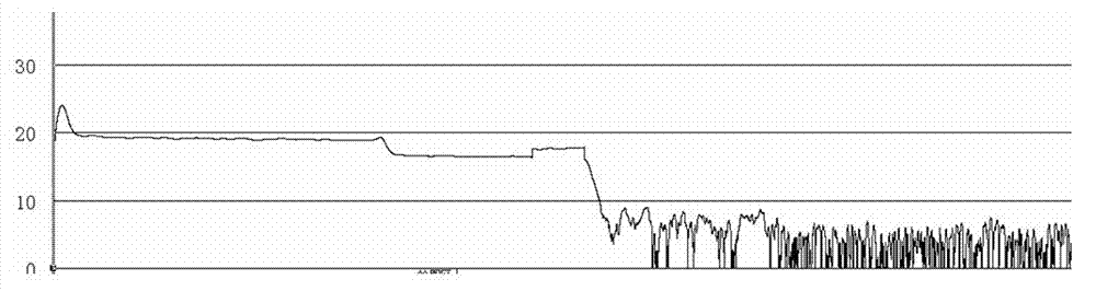
[0024] (1) Using coherent optical time-domain reflectometry and Rayleigh scattering technology to extract the information of each point of the optical cable carried by Rayleigh scattered light, and initially determine the OTDR curve of the optical cable at this time and the approximate location of the cable fault point A; the...


PUM


Abstract

The invention discloses a method for precisely positioning a fault of an optical cable by utilizing rayleigh scattering and coherent optical time domain reflection technology. The method comprises the following steps of utilizing the coherent optical time domain reflection and rayleigh scattering technology, wherein rayleigh scattered light carries each distributed point information of the optical cable according to the optical time domain reflection principle, and the distributed point information of the optical cable comprises strength information caused by loss and phase information of an interferometer based on Sagnac ring principle caused by external disturbance; testing the positioning of the optical cable by combining an ultrasonic vibrator with a Rayleigh scattered optical time domain reflectometer, finding out the position of a vibration point, re-utilizing a method of combining absolute positioning with relative positioning, and carrying out successive approximation to finally realize precise positioning of the optical cable. Compared with the prior art, the method for precisely positioning the fault of the optical cable by utilizing the rayleigh scattering and coherent optical time domain reflection technology, disclosed by the invention, has the advantages of simplicity in operation, small calculated amount, shortened time for finding out a fault point and reduced maintenance cost.

Description

technical field [0001] The invention relates to a method for locating a fault point of an optical cable line, in particular to a method for accurately locating an optical cable fault by using Rayleigh scattering and coherent optical time domain reflection technology. Background technique [0002] Since the 1990s, with the rapid development of communication technology and the increasing demand for communication network bandwidth, the application of optical fiber communication has become more and more extensive, and it has now occupied a dominant position. As of June 2012, the total length of national communication optical cable lines reached 13.432 million kilometers, and a communication optical cable network covering the whole country has been built. With the increase in the number of optical cables and the aging of early-laid optical cables, the number of faults in optical cable lines is increasing. The traditional optical cable line maintenance management mode is difficul...

Claims


Application Information

Patent Timeline
Patent Type & Authority Applications(China)
IPC IPC(8): H04B10/071
Inventor 陈溢文赵奎黄凤玲文金朝
Owner GUILIN G LINK TECH
Why Eureka
Try Eureka