Dilatation Catheter

A technology for dilating catheters and catheter shafts, applied in catheters, balloon catheters, etc., can solve the problem of difficult extraction of balloon catheters, and achieve the effects of preventing breakage, reducing deflection, and preventing falling off

Active Publication Date: 2013-04-17
GOODMAN & COMPANY
View PDF8 Cites 7 Cited by
  • Summary
  • Abstract
  • Description
  • Claims
  • Application Information

AI Technical Summary

Problems solved by technology

[0003] On the other hand, the inventors of the present application have found that the elongated member has the following problem, that is, when the balloon is deflated to extract the bal

Method used


Image

  • Dilatation Catheter
  • Dilatation Catheter
  • Dilatation Catheter

Examples


Example

[0061] (First embodiment)

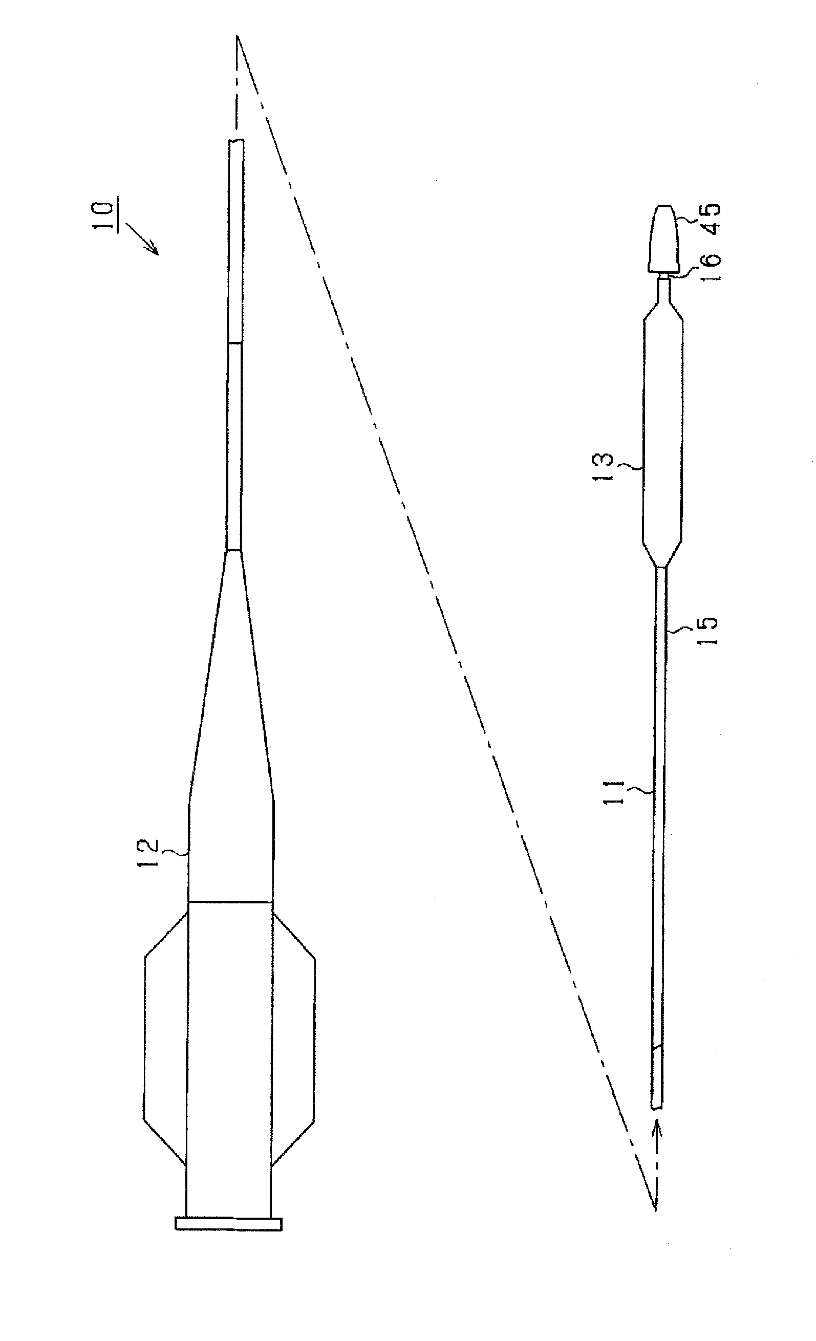
[0062] Hereinafter, a first embodiment embodying the present invention will be described based on the drawings. figure 1 It is a brief overall side view of the balloon catheter 10.

[0063] Such as figure 1 As shown, the balloon catheter 10 has: a catheter tube (catheter shaft) 11, a sleeve 12 attached to the proximal end (base end) of the catheter tube 11, and the distal end of the catheter tube 11 (Front end) of the balloon 13.

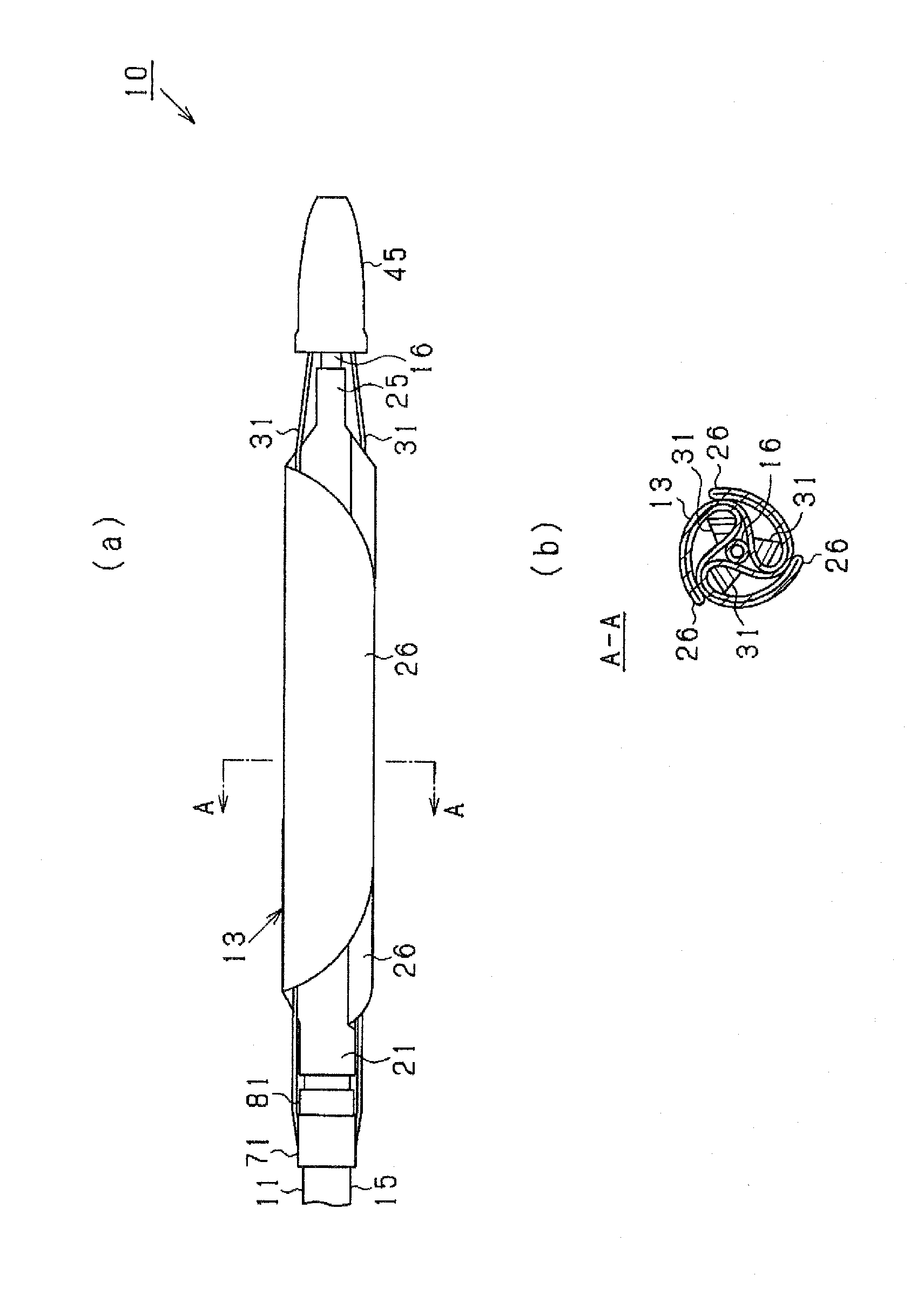
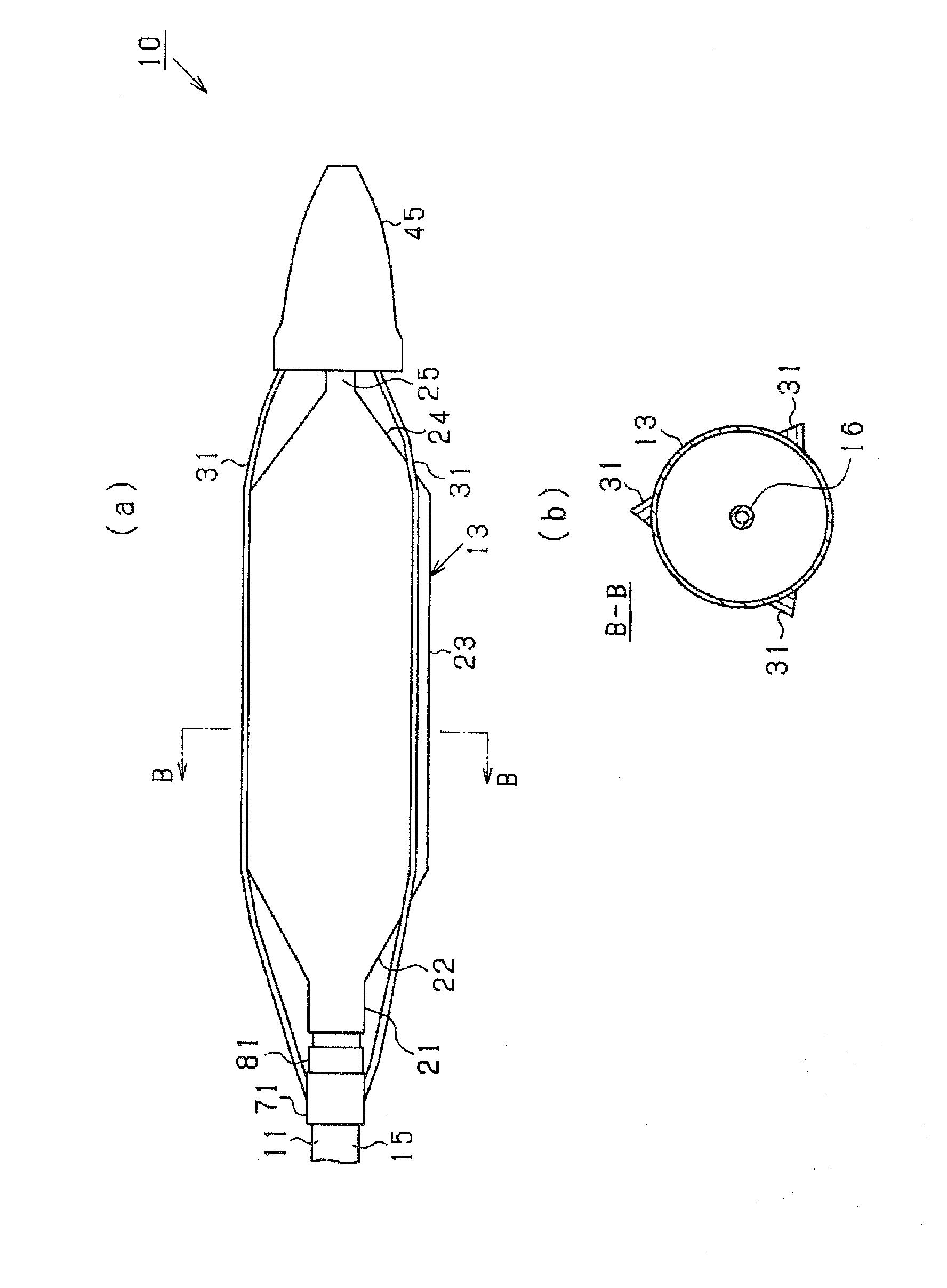
[0064] The catheter tube 11 is composed of a plurality of tubes (tubular shafts), and has an inner-outer multi-tube structure (inner-outer double-tube structure) at least from a midway position in the longitudinal direction (axial direction) to the position of the balloon 13. Specifically, the catheter tube 11 has an outer tube (outer tube) 15 and an inner tube (inner tube) 16 having a smaller inner diameter and outer diameter than the outer tube 15, and the inner tube 16 is inserted into the outer tube 15 to form the above Mu...

Example

[0098] (Second embodiment)

[0099] Figure 7 It is a cross-sectional view showing the balloon catheter 10a of the second embodiment. The balloon catheter 10a is different from the first embodiment in that it is equipped with an urging spring 79 between the stopper 81 and the movable mounting member 71. The urging spring 79 can absorb the remaining length of the linear member 31 by the urging force when the balloon 13 is contracted, so that the deflection of the linear member 31 can be further reduced.

[0100] The force spring 79 can not only be Figure 7 The illustrated metal coil spring may be, for example, a resin member having a spring function formed by using an elastic polyamide-based elastomer as a base material. It should be noted that the urging spring 79 is also called a urging member.

[0101] For example, when the bending rigidity of the linear member 31 is small and it is difficult to expect a restoring force, or when the balloon 13 is set to be long to cope with a lo...


PUM


Abstract

Provided is a technology for suppressing the trapping of an elongated element included in a balloon catheter. The present invention provides a dilatation catheter. This dilatation catheter (10) comprises: catheter shafts (15, 16); a dilatation element (13) connected to one end of the catheter shaft and having a dilatation area to be dilated in the diametrical direction; and an elongated element (31) arranged along the outer circumferential surface of the dilatation area and deforming outward along with the dilatation of the dilatation area by being mounted on the catheter shafts (15, 16) at a first mounting position and a second mounting position across the dilatation area. The dilatation catheter is characterized in that a specific mounting position (45b, 71) that is at least one of the first and second mounting positions is movable relative to the catheter shafts (15, 16), and that the movement of the specific mounting position is restricted in the restricting direction that is at least one direction.

Description

technical field [0001] The present invention relates to a balloon catheter which is inserted into a living body and used for dilation treatment of a narrowed part or a blocked part of a blood vessel. Background technique [0002] Conventionally, balloon catheters have been used for treatments such as PTCA (percutaneous transluminal coronary angioplasty). It has also been proposed for balloon catheters to have an elongated element around the balloon. For example, in the balloon catheter disclosed in Patent Document 1, an elongated element is provided on the outer peripheral side of the balloon so as to straddle the balloon in the longitudinal direction. The elongated element can engage the lesion with the inflation of the balloon, thereby forming a lumen (flow path) in the axial direction in the lesion. The elongated element also has the effect of being able to inhibit slippage between the balloon and the lesion. [0003] On the other hand, the inventors of the present app...

Claims


Application Information

Patent Timeline
IPC IPC(8): A61M25/00
CPCA61M25/10A61M25/1006A61M2025/105A61M2025/1081A61M2025/1093
Inventor 岩野健志三宅孝政
Owner GOODMAN & COMPANY
Why Eureka
Try Eureka