Photoacoustic imaging device free of limitation of ultrasonic transducer frequency bands and detection method of photoacoustic imaging device

An ultrasonic transducer and frequency band limitation technology, which is applied in ultrasonic/sonic/infrasonic diagnosis, acoustic diagnosis, infrasonic diagnosis, etc., can solve problems such as narrow frequency band and irreconcilability, and achieve clinical promotion, low requirements for imaging environment conditions, Get rid of the effect of bandwidth limitation defect

Inactive Publication Date: 2014-11-05
SOUTH CHINA NORMAL UNIVERSITY
View PDF3 Cites 0 Cited by
  • Summary
  • Abstract
  • Description
  • Claims
  • Application Information

AI Technical Summary

Problems solved by technology

[0003] Traditional photoacoustic signal detection tools are generally ultrasonic transducers, and photoacoustic signals have a wide frequency band, but traditional ultrasonic transducers are limited by materials, and generally have narrow frequency bands, and broadband photoacoustic signals have narrower frequency bands. The detectors form an irreconcilable contradiction

Method used


Image

  • Photoacoustic imaging device free of limitation of ultrasonic transducer frequency bands and detection method of photoacoustic imaging device
  • Photoacoustic imaging device free of limitation of ultrasonic transducer frequency bands and detection method of photoacoustic imaging device
  • Photoacoustic imaging device free of limitation of ultrasonic transducer frequency bands and detection method of photoacoustic imaging device

Examples


Embodiment 1

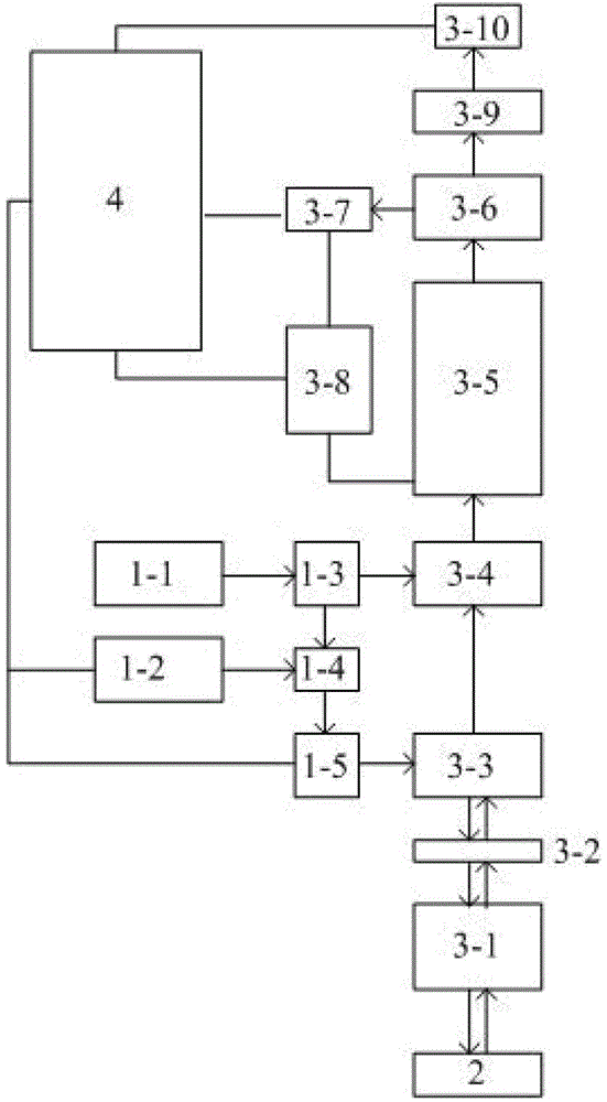
[0042] Such as figure 1 As shown, a photoacoustic imaging device without ultrasonic transducer frequency band limitation, including a photoacoustic excitation component, a photoacoustic signal detection component, a photoacoustic signal acquisition / processing component 4 and a sample stage 2, the photoacoustic excitation component , the photoacoustic signal detection component is connected to the photoacoustic signal acquisition / processing component in sequence, the photoacoustic excitation component is connected to the photoacoustic signal acquisition / processing component, and the photoacoustic signal detection component is connected to the sample stage 2;

[0043] The photoacoustic excitation component includes a photoacoustic signal detection light source 1-1, a beam splitter 1-3, a dichroic mirror 1-4, a photoacoustic excitation light source 1-2, and a two-dimensional scanning galvanometer 1-5. Acoustic signal detection light source 1-1, beam splitter 1-3, dichroic mirror ...

Embodiment 2

[0057] The detection method using the photoacoustic imaging device without ultrasonic transducer frequency band limitation of Example 1 includes the following steps:

[0058] (1) Inject 0.5mL of 2% pentobarbital sodium solution into a two-week-old Kunming mouse. After the mouse is anesthetized, remove the hair on the back of the mouse with human depilatory cream, and then place the mouse in the sample place it on the table and fix it;

[0059] (2) The photoacoustic signal detection component is placed directly above the surface of the mouse; the height of the sample stage is adjusted so that the detection light is focused on the surface of the back of the mouse;

[0060] (3) The photoacoustic excitation light and the photoacoustic signal detection light are combined into a beam of light through a dichroic mirror, and then irradiated to the surface of the back of the mouse through a two-dimensional scanning galvanometer, a polarizing beam splitter A and a flat objective lens, s...


PUM


Abstract

The invention discloses a photoacoustic imaging device free of limitation of ultrasonic transducer frequency bands and a detection method of the photoacoustic imaging device. The photoacoustic imaging device comprises a photoacoustic excitation assembly, a photoacoustic signal detection assembly, a photoacoustic signal collection / processing assembly and a sample platform, the photoacoustic excitation assembly, the photoacoustic signal detection assembly and the photoacoustic signal collection / processing assembly are sequentially connected, the photoacoustic excitation assembly and the photoacoustic signal collection / processing assembly are connected, and the photoacoustic signal detection assembly is connected with the sample platform. According to the photoacoustic imaging device, pulse lasers are used for radiating a biological sample to generate photoacoustic signals, continuous lasers with narrow line width are focused on the surface of the sample, vibration speeds of the surface of the sample are detected to achieve the purpose of detecting the photoacoustic signals, the defect of bandwidth limitation of the transducer is overcome, and the defects that high frequency photoacoustic signals are sharply attenuated in biological tissues and can not be detected are overcome; detection portions are not required to be subjected to any processing, requirements for imaging environment conditions are low, and large pushing functions on clinical performances of photoacoustic technology are achieved.

Description

technical field [0001] The invention belongs to the technical field of photoacoustic imaging, and in particular relates to a photoacoustic imaging device without frequency band limitation of an ultrasonic transducer and a detection method thereof. Background technique [0002] When a certain absorber is irradiated with light, the absorber absorbs the light energy and produces a temperature rise, and the temperature rise and fall causes the volume of the absorber to expand and shrink, and ultrasonic waves are generated. This phenomenon is called the photoacoustic effect. The photoacoustic effect has attracted people's attention since it was discovered in the 19th century, and it has been applied in various fields to varying degrees. As a new imaging technology, photoacoustic imaging has been applied in more and more fields. This imaging technology uses short-pulse laser as the excitation source, and the ultrasonic signal excited by it as the information carrier. By reconstru...

Claims


Application Information

Patent Timeline
Patent Type & Authority Patents(China)
IPC IPC(8): A61B8/00
Inventor 杨思华陈重江邢达
Owner SOUTH CHINA NORMAL UNIVERSITY
Why Eureka
Try Eureka