
Cooling device used in respirator

A technology for cooling devices and respirators, which is applied in the direction of respiratory protection devices and life-saving equipment, etc. It can solve the problems that affect the application development and marketing of chemical oxygen respirators, the overheating of the gas inhaled by the wearer, and the lack of cooling and cooling devices, etc., so as to achieve convenience Large-scale production, easy operation, and the effect of increasing heat transfer

Active Publication Date: 2013-04-24
BEIJING ANYANGTE TECH
View PDF4 Cites 7 Cited by
  • Summary
  • Abstract
  • Description
  • Claims
  • Application Information

AI Technical Summary

Problems solved by technology

In many environments, due to overheating of the ambient temperature, or a large amount of heat generated in the process of producing oxygen (chemical oxygen respirator), the wearer's inhaled gas is overheated and the breathing comfort is not high
[0004] At present, the existing chemical oxygen respirators on the market are not equipped with cooling and cooling devices, and the problem of oxygen production and heat release through chemical reactions has not been solved, thus affecting the further application development and marketing of chemical oxygen respirators; and compressed oxygen The respirator only has a simple dry ice (blue ice) storage box, no professional cooling device, complicated operation and poor cooling effect

Method used


Image

  • Cooling device used in respirator
  • Cooling device used in respirator
  • Cooling device used in respirator

Examples


specific Embodiment 1

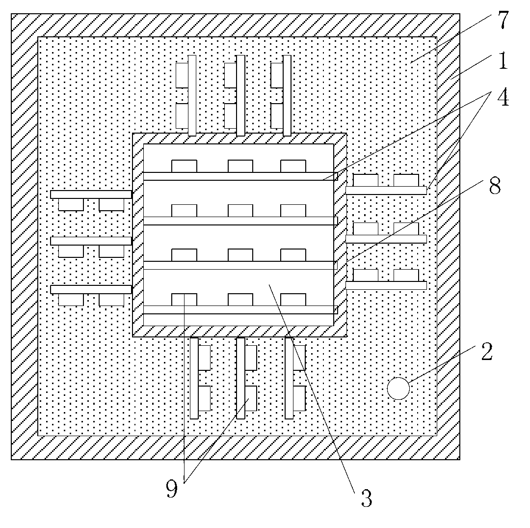
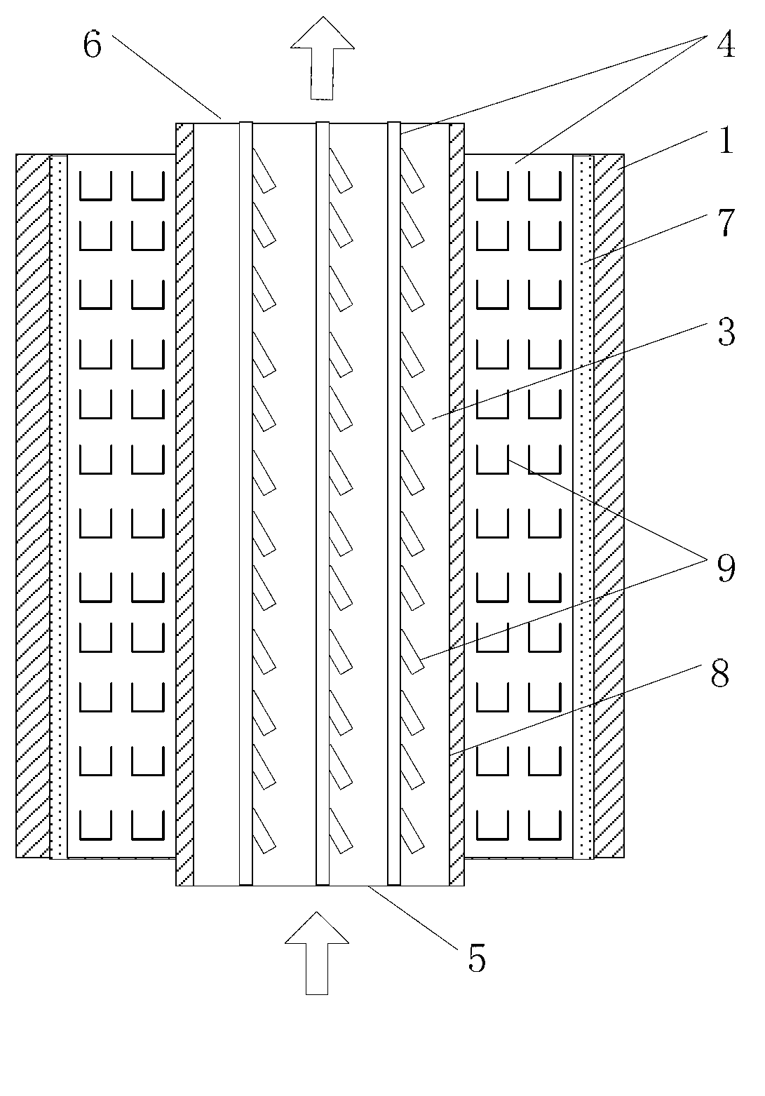
[0028] figure 1 , figure 2 They are the cross-sectional schematic diagram and the cross-sectional schematic diagram of the cooling device according to the first embodiment of the present invention. The cooling device includes a device housing (1) and an airflow cylinder (8). The housing (1) is a rectangular parallelepiped tank, and the rectangular parallelepiped tank The length of the bottom surface is 15cm, and the height is 18cm. The airflow cylinder is a square cylinder coaxial with the cooling device housing (1). An airflow channel (3) is formed inside the airflow cylinder. The airflow direction is as follows: figure 2 arrow direction. A closed cavity is formed between the casing (1) and the airflow cylinder (8), and the closed cavity is filled with coolant (7).

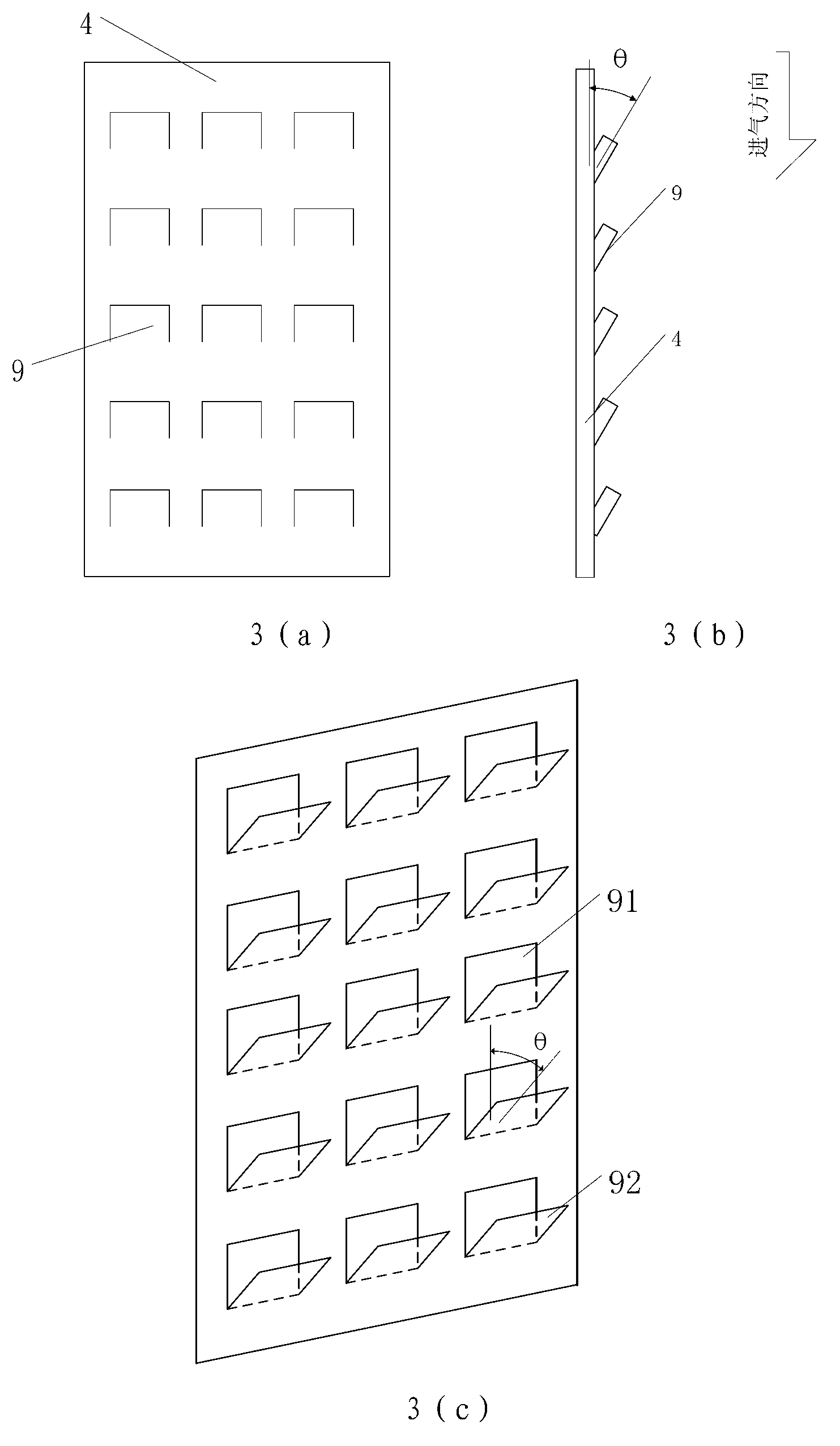
[0029] A plurality of heat exchange fins (4) are distributed inside and outside the airflow cylinder (8), and the heat exchange fins (4) are parallel to the airflow direction in the airflow cylinder (8). T...

specific Embodiment 2

[0034] Such as Figure 4 As shown, the device casing (1) of the cooling device in this embodiment is a cylindrical tank body, the diameter of the bottom surface of the cylindrical tank body is 10 cm, and the height is 27 cm. The airflow cylinder is a cylinder coaxial with the housing (1) of the cooling device, and an airflow channel (3) is formed inside the airflow cylinder. The airtight cavity formed between the casing (1) and the airflow cylinder (8) is filled with organic nano-cooling material as a coolant (7). The melting point of the cooling material is between 5 degrees Celsius and 35 degrees Celsius, and the heat of fusion is 100kJ / Between kg and 2000kJ / kg, the temperature is lowered by melting and absorbing heat.

[0035] A plurality of heat exchange fins (4) are distributed inside and outside the airflow cylinder (8), and the heat exchange fins (4) are parallel to the airflow direction in the airflow cylinder (8). The internal heat exchange fins (4) of the airflow ...


PUM


Abstract

The invention provides a cooling device used in a respirator. The cooling device comprises a shell body (1) and an air flow barrel, a sealing cavity is formed between the shell body and the air flow barrel and used for accommodating cooling agent, and the inner wall and the outer wall of the air flow barrel are respectively provided with heat exchange sheets. High temperature oxygen in the respirator inters into the air flow barrel, blocked by a guide flow blocking plate of the heat exchange sheets inside the air flow barrel, and guided to guide flow holes; accordingly heat conduction performance is enhanced, heat of high temperature air is quickly transmitted to the outside of the air flow barrel and then performed with fusing heat absorption through the cooling agent to efficiently lower temperature, temperature of the high temperature air is brought out, and further temperature of the high temperature air is quickly dropped to below 35 DEG C to be provided for human bodies to breathe. The cooling device used in the respirator effectively solves the cooling problem of rescue and working respirator; overcomes the shortcomings that existing chemical oxygen generation respirators are not provided with cooling devices, can only be applied to self-rescue, and cannot be used for working; expands application range of rescue and working respirators, enables respirator users to be more comfortable and smoother in breathing, and ensures safety of the users.

Description

technical field [0001] The invention relates to the field of respiratory protectors, in particular to a cooling device in the respirator. [0002] Background technique [0003] Rescue and working respirators are used to enter wells or protect personnel in underground mines or in special environments. the fire , gas It is a portable respiratory protective device to prevent the human body from inhaling harmful gas poisoning or hypoxia suffocation during accidents such as , coal dust explosion, etc. Its main purpose is to wear it for users to avoid danger from poisoning or suffocation when various accidents occur; it is suitable for marine ships, underground railways, harmful gas storage warehouses, entertainment venues, large shopping malls and high-rise residential buildings and other places. In order to meet the requirements of escape and rescue in special environments, many countries in the world have increased the research on various respirators, and gradually develope...

Claims


Application Information

Patent Timeline
Patent Type & Authority Applications(China)
IPC IPC(8): A62B9/00
Inventor 唐启明车晓葵刘文海束克庆巩素珍黄召张红红
Owner BEIJING ANYANGTE TECH
Learn More