
Inertia gravity dust collector

A dust collector and gravity technology, applied in chemical instruments and methods, dispersed particle separation, combined devices, etc., can solve the problems of high operating resistance, investment, high operating cost, and large volume of bag dust collectors, and achieve dust collection Remarkable effect, reduced operating cost, and low operating resistance

Active Publication Date: 2013-04-24
HUBEI JINLU ENERGY SAVING LTD CO
View PDF5 Cites 14 Cited by
  • Summary
  • Abstract
  • Description
  • Claims
  • Application Information

AI Technical Summary

Problems solved by technology

[0003] The purpose of the present invention is to overcome the problems of high running resistance, large volume, high investment and operating costs of the bag filter, and provide an inertial gravity dust collector for pre-treatment of the bag filter

Method used


Image

  • Inertia gravity dust collector
  • Inertia gravity dust collector
  • Inertia gravity dust collector

Examples


example 1

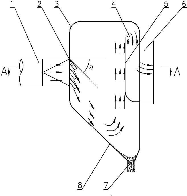
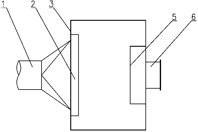
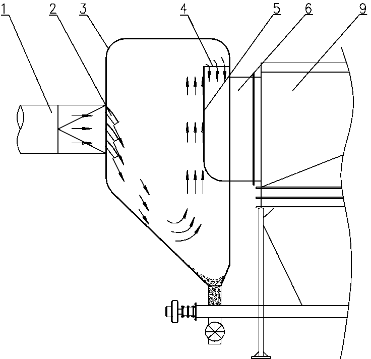
[0022] Example 1: see figure 1 , 2 , the structure of the present invention has a housing 3, especially: a smoke inlet pipe 1 is installed in the left middle part of the housing 3, an ash outlet pipe 7 is installed at the bottom of the housing 3, and an ash outlet pipe 7 is installed on the right side wall of the housing 3. A smoke exhaust pipe 6 is provided, and a guide coaming plate 5 is provided at the inner mouth of the smoke exhaust pipe 6 to form an upper entrance structure, and the upper entrance is higher than the smoke inlet pipe 1; the housing 3 is located on the smoke inlet pipe 1 There are three layers of arc-shaped deflectors 2 at the mouth of the nozzle (the number of layers is designed according to the furnace type, working conditions and other conditions, and at least one layer is guaranteed), which is directed downward, and the tangent direction of the starting point of the arc-shaped deflectors 2 is in line with the horizontal direction. The direction of smo...

example 2

[0025] Example 2: structure two of the present invention, see Figure 4 , it has a housing 3, in particular: a smoke inlet pipe 1 is installed in the middle of the left side of the housing 3, an ash outlet pipe 7 is installed at the bottom of the housing 3, and a smoke exhaust pipe 6 is arranged on the top of the housing 3 and a five-layer arc-shaped deflector 2 is arranged at the nozzle of the smoke inlet pipe 1 on the shell 3, which is directed downward, and the tangent direction of the starting point of the arc-shaped deflector 2 is α' to the horizontal smoke flow direction =35° angle arrangement.

[0026] In this embodiment, the lower part of the right side wall of the housing 3 is an inclined wall surface 10 .

[0027] The second structure of the present invention can be directly placed at the outlet end of the dryer cylinder where the material brought out by the increase of the wind speed in the output lifting cylinder increases sharply, which can reduce the pressure of...


PUM


Abstract

The invention relates to environmental protection equipment, and discloses an inertia gravity dust collector applied to industrial production. The inertia gravity dust collector is provided with a shell and is characterized in that the middle of one side of the shell is provided with a smoke inlet pipe, the bottom of the shell is provided with a dust outlet pipe, a smoke discharging pipe is arranged on the top or the side wall of the shell, and a plurality of guide plates with a downward guiding direction are arranged on the shell and at the opening of the smoke inlet pipe. The inertia gravity dust collector provided by the invention has the advantages of simple structure, small resistance, low manufacturing cost and remarkable dust collection effect, is mainly used for preprocessing of a bag collector and other dust collectors, and can be used for improving the treatment efficiency and effects of the bag collector and the other tail end dust collectors.

Description

technical field [0001] The invention relates to environmental protection equipment, in particular to an inertia gravity dust collector. Background technique [0002] With the wide application of wind separation technology in industrial production, the bag filter is not only an air purifier, but also a collector of materials (products). For example, the output of Φ6.3 vertical mill in fine powder production is 255t / h , the 255t / h qualified micro-powder is collected and stored in the bag filter at the end by wind sorting. The dust concentration entering the bag filter is about 500g / Nm 3 , namely 500000Mg / Nm 3 , purified to 30Mg / Nm 3 Emission, the ratio is 16666.7 times. In order to increase the life of the bag and reduce the resistance, that is, reduce the power consumption of the induced draft fan, the filter wind speed of the bag is usually reduced from 1 to 1.2m / min to 0.4 to 0.5m / min, and its volume is increased by one more than double the cost. The engineering field...

Claims


Application Information

Patent Timeline
IPC IPC(8): B01D45/02B01D45/04B01D50/00
Inventor 熊承庆童珍张丹黄萌
Owner HUBEI JINLU ENERGY SAVING LTD CO
Learn More