Pipe cutter

A technology for cutting pipes and tool holders, which is applied in the direction of pipe shearing devices, knives for shearing machine devices, shearing devices, etc., which can solve the problems of easy scratching of the inner wall of the pipe by chips, easy heating of the cutter head, and poor cutting quality. It achieves the effect of convenient and fast disassembly and operation, reduced working procedures and long service life

Inactive Publication Date: 2013-04-24
HARBIN TIANTAI TECH
View PDF7 Cites 8 Cited by
  • Summary
  • Abstract
  • Description
  • Claims
  • Application Information

AI Technical Summary

Problems solved by technology

[0002] At present, domestic heat exchanger factories basically use a tool called a tube cutter to cut off the excess part of the expanded heat exchange tube during the production process. The principle is to use a special tool holder to fix the turning tool. Then the electric device is used to complete the task of cutting the pipe head. This method belongs to chip processing, that is, the cutting head is used for cutting, which is easy to hit the knife, the head is easy to heat, and the service life is short. Moreover, the chip is easy to scratch the inner wall of the pipe, and the cutting quality is poor.

Method used


Image

  • Pipe cutter
  • Pipe cutter
  • Pipe cutter

Examples


Embodiment Construction

[0015] The embodiments of the present invention will be described in further detail below with reference to the accompanying drawings.

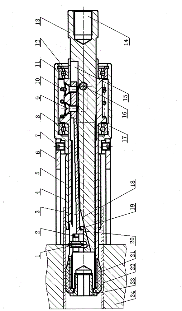
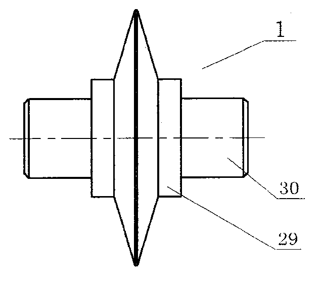
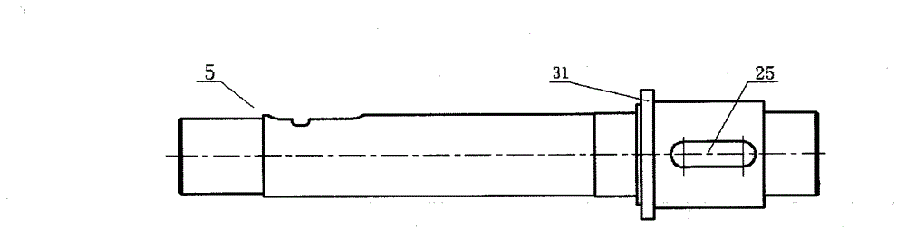
[0016] Depend on Figure 1-Figure 5 It can be seen that the present invention includes a knife rod 13 and a knife holder 2. The knife rod 13 is installed in the middle cavity of the holding sleeve 5, and the upper part is provided with a groove 15, and the groove 15 is equipped with a leaf spring 3, and the leaf spring 3 passes through the screw. 9 is connected to the retaining sleeve 5. The outer sleeve of the retaining sleeve 5 is sheathed with a left rolling bearing 8 and a right rolling bearing 11. The retaining sleeve 5 between the left rolling bearing 8 and the right rolling bearing 11 has an oblong through hole 25 on the wall. A spring 10 is set on the sleeve, the left end of the spring 10 is placed on the shoulder 31 of the retaining sleeve 5, and the right end is placed on the positioning pin 16 inserted in the cutter bar 13, and the...


PUM


Abstract

The invention relates to a pipe cutter. The pipe cutter comprises a cutter bar and a cutter rest, wherein the cutter bar is installed in a hollow cavity of a keeping sleeve and provided with a groove on the upper portion, a plate spring is connected with the keeping sleeve through a screw, a long and round through hole is arranged on the wall of the keeping sleeve between a left rolling bearing and a right rolling bearing, a spring is sleeved outside the keeping sleeve, a blind hole with threads is arranged on the right side of the cutter bar, a cutter rest leaning slope is arranged on the left side, the cutter rest leans against the cutter rest leaning slope, a round cutter is mounted on the cutter rest, and a cutter rest hook is arranged at the right end and connected with a plate spring hook arranged at the left end of the plate spring in a hooking mode. The pipe cutter is simple in structure and compact in structure, reasonable in design, capable of bearing large load, safe and reliable; cleaning operation is not needed due to scrap-free cutting, operating processes are reduced, no scrap scratches inner walls of pipes, the cutting quality is high, the service life is long, and high economic benefits are provided.

Description

technical field [0001] The present invention relates to a kind of cutter, in particular to a kind of cutting cutter for cutting off the redundant part of the heat exchange tube on the heat exchanger. Background technique [0002] At present, domestic heat exchanger factories basically use a tool called a tube cutter to cut off the excess part of the expanded heat exchange tube during the production process. The principle is to use a special tool holder to fix the turning tool. Then, the task of cutting off the pipe head is completed by the electric device. This method belongs to chip processing, that is, the cutting tool is used for cutting, which is easy to cut, the tool head is easy to heat, and the service life is short, and the chips are easy to scratch the inner wall of the pipe, and the cutting quality is poor. SUMMARY OF THE INVENTION [0003] The purpose of the present invention is to overcome the deficiencies existing in the above-mentioned technologies, and to pr...

Claims


Application Information

Patent Timeline
Patent Type & Authority Applications(China)
IPC IPC(8): B23D21/14B23D35/00
Inventor 胡乃文于广滨丁永生
Owner HARBIN TIANTAI TECH
Why Eureka
Try Eureka