Shaft gear composite processing machine tool

A composite processing and gear technology, applied in the direction of belt/chain/gear, gear teeth, mechanical equipment, etc., can solve the problems of low degree of automation, low gear processing efficiency, waste of resources, etc., to reduce production costs, save conversion time, The effect of guaranteed machining accuracy

Active Publication Date: 2013-04-24
CHONGQING MACHINE TOOL GROUP
10 Cites 18 Cited by

AI-Extracted Technical Summary

Problems solved by technology

The production line is organized in the form of multiple stand-alone clusters for gear processing. On the one hand, the dispersion of multiple processes results in repeated clamping, positioning and tool setting of the gear workpiece, which makes it difficult to guar...

Abstract

The invention relates to a shaft gear composite processing machine tool which comprise a tool body, a column, a rotary working platform, a hob feeding mechanism, a supporting frame feeding mechanism and a rotary knife tower feeding mechanism, wherein the column, the rotary working platform, the hob feeding mechanism, the supporting frame feeding mechanism and the rotary knife tower feeding mechanism are fixed on the tool body. The rotary working platform is fixed on the top surface of the tool body, and the hob feeding mechanism, the supporting frame feeding mechanism and the rotary knife tower feeding mechanism are horizontally and sequentially arranged on one side of the column close to the rotary working platform and matched with the column in the vertical direction in sliding mode. A workpiece is clamped once, turning, hobbing, milling, chamfering, burring, drilling and the like are performed on gears of different sizes through rotation of the working platform, switch of different processing knives, horizontal and longitudinal feeding and rotation of angles. Switching time of the workpiece between different machine tools is saved, processing efficiency is improved, and processing precision of parts is guaranteed to the maximum limit.

Application Domain

Technology Topic

Image

  • Shaft gear composite processing machine tool
  • Shaft gear composite processing machine tool
  • Shaft gear composite processing machine tool

Examples

  • Experimental program(1)

Example Embodiment

[0031] Hereinafter, the preferred embodiments of the present invention will be described in detail with reference to the accompanying drawings.
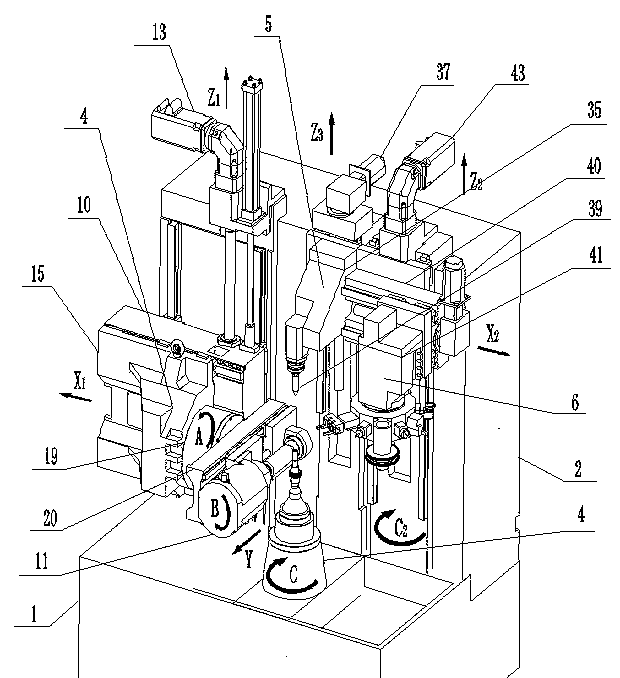
[0032] As shown in the figure, a shaft gear composite machining machine tool of the present invention includes a bed 1, a column fixed on the bed 1, a rotating table 3, a hob feeding mechanism 4, and a support frame feeding mechanism 5. And the rotary turret feed mechanism 6; the rotary table 3 is fixed on the top surface of the bed 1; the hob feed mechanism 4, the support frame feed mechanism 5 and the rotary turret feed mechanism 6 are arranged laterally in sequence The upright column 2 is close to the side of the rotating worktable 3 and is slidingly fitted with the upright column 2 in the vertical direction. Place the workpiece on the rotary table 3, the support frame feeding mechanism 5 slides up and down according to the height of the workpiece to adjust and fix the workpiece to rotate on the rotary table 3, the hob feeding mechanism 4, and the rotary turret feeding mechanism 6 Slide up and down according to different processing positions of the workpiece, and use the tool installed on it to process the workpiece.
[0033] figure 2 It is a cross-sectional view of the rotary table of the present invention. As shown in the figure, the rotary table 3 includes a table 7 and an electric spindle I8. The electric spindle I8 is arranged in the rotary table 3, and the table 7 is arranged on the rotary table 3. On the top surface, the main shaft I9 of the electric main shaft I8 is in transmission cooperation with the worktable 7. The spindle I9 is ​​connected with the worktable surface 7. After the electric spindle I8 is started, the worktable surface 7 is driven to rotate in the C direction, and the workpiece is placed on the worktable surface 7, and the workpiece rotates to meet the processing needs.
[0034] image 3 The hob feed mechanism Z of the present invention 1 Directional sectional view, as shown in the figure, the hob feed mechanism 4 includes a sliding plate I10, a hob holder 11, a hob feed screw 12 fixed on the column 2 and a transmission cooperation with the hob feed screw 12 The hob feed servo motor 13; the hob holder 11 is connected to the sliding plate I10, and the sliding plate I10 is provided with a screw sleeve I14 corresponding to the hob feed screw 12. The hob feed servo motor 13 drives the hob feed screw 12 to rotate, and the slide Ⅰ10 moves along Z 1 Move in the axial direction, so as to achieve the purpose of longitudinal feeding of the hob feeding mechanism 4.
[0035] Figure 4 The hob feed mechanism X of the present invention 1 As shown in the figure, the hob feed mechanism 4 also includes a sliding plate Ⅲ 15 arranged on the side of the sliding plate Ⅰ 10 away from the upright column 2. The sliding plate Ⅲ 15 and the sliding plate Ⅰ 10 slidably cooperate with each other. The feed screw 16 and the transverse feed servo motor 17 which is driven and matched with the transverse feed screw 16 are provided with a screw sleeve II 18 corresponding to the transverse feed screw 16 on the sliding plate I10. The lateral feed servo motor 17 drives the lateral feed screw 16 to rotate, so that the slide plate Ⅲ 15 is along X 1 Move in the axial direction, so as to achieve the purpose of the hob feeding mechanism 4 to feed the knife horizontally.
[0036] Figure 5 Sectional view of the rotating mechanism of the hob holder of the present invention Figure Ⅰ , Image 6 Sectional view of the rotating mechanism of the hob holder of the present invention Figure II As shown in the figure, the hob feed mechanism 4 also includes a hob rotation mechanism 19 arranged on the slide plate III 15 near the side of the rotating table 3 along the sliding direction. The hob rotation mechanism 19 includes a base 20 and a rotating shaft. 21. Worm gear pair and the hob rotation servo motor 22 corresponding to the worm gear pair. The worm gear pair includes a worm wheel 23 connected to the rotating shaft 21 and a worm 24 corresponding to the worm wheel. The hob rotation servo motor 22 and the worm 24 are correspondingly driven In cooperation, the rotating shaft 21 is arranged along the sliding direction of the sliding plate III15, and one end of the rotating shaft 21 close to the rotating worktable 3 is connected to the base 20. The hob rotation servo motor 22 drives the worm 24 to rotate, and drives the rotation shaft 21 connected with the worm wheel 23 to rotate. The rotation shaft 21 drives the base 20 to rotate in the A direction, so that the hob 11 produces different angles and can achieve straightness. Machining of teeth and helical teeth.
[0037] Figure 7 It is a cross-sectional view in the Y direction of the hob feed mechanism of the present invention. As shown in the figure, the hob feed mechanism 4 further includes a hob feed screw provided on the side of the base 20 away from the hob rotation mechanism 19 25 and a hob feed servo motor 26 that is driven and matched with the hob feed screw 25, and the hob 11 is provided with a screw sleeve III 26 corresponding to the hob feed screw 25. The hob feed servo motor 26 drives the hob feed screw 25 to rotate, so that the hob 11 moves along the Y-axis direction, so as to meet the requirements of the hob feed mechanism 4 for processing parts of different sizes.
[0038] Figure 8 It is a cross-sectional view of the hob of the present invention. As shown in the figure, the hob 11 includes a left tool holder 27 and a right tool holder 28. The right tool holder 28 is provided with an electric spindle Ⅱ 29, and the left tool holder 27 is provided with an electric The sliding seat 31 corresponding to the direction of the spindle Ⅱ30 of the spindle Ⅱ29 is provided with a hob 32 between the spindle Ⅱ30 and the sliding seat 31. One end of the spindle Ⅱ30 is matched with the hob 32 in transmission, and the other end of the hob 32 is in rotation with the sliding seat 31. ; The left tool holder 27 is provided with a tool holder screw 33, and the right tool holder 28 is provided with a tool holder shaft sleeve 34 corresponding to the tool holder screw 33. Install the hob 32 between the spindle Ⅱ30 and the sliding seat 31, adjust the tool post screw 33 to fix the hob 32, after the electric spindle Ⅱ29 is started, the spindle Ⅱ30 drives the hob 32 to rotate in the B direction, thereby hob The feed mechanism 4 performs tooth profile processing on the workpiece.
[0039] Picture 9 It is the support frame feeding mechanism Z of the present invention 3 As shown in the figure, the supporting frame feeding mechanism 5 includes an outer frame 35, an outer frame feeding screw 36 fixed on the column 2 and an outer frame feeding screw 36 which is in cooperation with the outer frame feeding screw 36. Feed the servo motor 37; the outer bracket 35 is provided with a screw sleeve IV 38 corresponding to the outer bracket feed screw 36; the outer bracket 35 is provided with a vertically downward center 39, the center 39 and the spindle I9 concentric. After the shaft workpiece is clamped on the rotating worktable 3, the outer bracket 35 moves along Z 3 Move in the axis direction, and use the center 39 to fix the top of the shaft workpiece, so as to avoid the position deviation of the shaft workpiece during the machining process and cause the machining error.
[0040] Picture 10 The feed mechanism Z of the rotary turret of the present invention 2 Directional sectional view, as shown in the figure, the rotary turret feed mechanism 6 includes a sliding plate Ⅱ 40, a rotary turret 41, a rotary turret feed screw 42 fixed on the column 2 and a rotary turret feed screw 42 42. The rotary turret feed servo motor 43 is matched with the transmission 42. The rotary turret 41 is connected with the sliding plate II 40, and the sliding plate II 40 is provided with a screw sleeve V 44 corresponding to the rotary turret feed screw 42. The rotary turret feed servo motor 43 drives the rotary turret feed screw 42 to rotate, so that the sliding plate Ⅱ40 moves along Z 2 Move in the axial direction, so that the longitudinal feed of the rotating tool post 41 is used to process the workpiece.
[0041] Picture 11 It is the rotary turret feed mechanism X of the present invention 2 As shown in the figure, the rotary turret feed mechanism 6 also includes a rotary turret feed screw 45 which is arranged on the side of the sliding plate II 40 away from the column 2 and is in cooperation with the rotary turret feed screw 45. The rotating tool post feed servo motor 46 is provided with a screw sleeve VI 47 corresponding to the rotating tool post feed screw 45 on the rotating tool post 41. The rotating tool post feed servo motor 46 drives the rotating tool post feed screw 45 to rotate so that the rotating tool post 41 moves along X 2 The axis moves, so that the rotating turret feed mechanism 6 can process parts of different sizes.
[0042] Picture 12 It is a cross-sectional view of the rotating tool post of the present invention. As shown in the figure, the rotating tool post 41 includes a cutter head 48, a gear pair 49, a vertically arranged transmission shaft 50 and a transmission drive servo motor 51 corresponding to the transmission shaft 50. The transmission drive servo motor 51 is matched with the transmission shaft 50 through a gear pair 49 corresponding to the transmission. The lower end of the transmission shaft 50 is provided with a bevel gear I52, and the cutter head 48 is provided with a bevel gear II53 to mesh with the bevel gear I52. The transmission drive servo motor 51 drives the transmission shaft 50 to rotate through the gear pair 49, and the bevel gear I 52 on the transmission shaft 50 drives the bevel gear II 53 to rotate, thereby realizing the rotation of the cutter head 48, and different tools can be selected to process the workpiece.
[0043] Figure 13 It is a three-dimensional schematic diagram of the rotating tool post of the present invention. As shown in the figure, the outer circle of the cutter head 48 is provided with a deburring device 54, a turning tool device 55, a cylindrical milling cutter device 56, an edge device 57, and a drill along the circumferential direction. Hole device 58 and manipulator device 59. Rotating the cutter head 48 and selecting different tools respectively can realize different processing procedures on the workpiece.
[0044] Finally, it should be noted that the above embodiments are only used to illustrate the technical solutions of the present invention and not to limit them. Although the present invention has been described with reference to the preferred embodiments of the present invention, those of ordinary skill in the art should understand that the Various changes can be made to the above and details without departing from the spirit and scope of the present invention defined by the appended claims.

PUM

no PUM

Description & Claims & Application Information

We can also present the details of the Description, Claims and Application information to help users get a comprehensive understanding of the technical details of the patent, such as background art, summary of invention, brief description of drawings, description of embodiments, and other original content. On the other hand, users can also determine the specific scope of protection of the technology through the list of claims; as well as understand the changes in the life cycle of the technology with the presentation of the patent timeline. Login to view more.

Similar technology patents

Image display circuit, image display method and image display device

ActiveCN112565585AReduce memory bandwidthReduced conversion timeTelevision system detailsColor television detailsData transmissionData input
Owner:GREE ELECTRIC APPLIANCES INC +1

Parking device of logistics tractor

PendingCN114103891AShort drive lineReduced conversion timeBraking element arrangementsBraking action transmissionElectric machineryDrive motor
Owner:湖南华菱汽车有限公司

Direct digital frequency synthesizer

Owner:INST OF SEMICONDUCTORS - CHINESE ACAD OF SCI

Classification and recommendation of technical efficacy words

  • Reduced conversion time
  • Improve processing efficiency

System and method for converting disordered point cloud to triangular net based on adaptive flatness

InactiveCN101067868AFast conversionReduced conversion timeFilling planer surface with attributesMesh gridAlgorithm
Owner:TONGJI UNIV

Subframe configuring method and system

ActiveCN102223604ATo achieve the purpose of saving electricity and energyReduced conversion timeBroadcast service distributionRadio transmission for post communicationElectricityConfiguration system
Owner:ZTE CORP

Method for realizing FFT (Fast Fourier Transform) with high point number

Owner:NO 54 INST OF CHINA ELECTRONICS SCI & TECH GRP

Acid tank sealing treatment system

Owner:YANTAI JEREH PETROLEUM EQUIP & TECH
Why Eureka
Try Eureka