Wheel track changing suspension mechanism of traveling machinery
A technology of variable wheelbase and suspension, which is applied in the field of motor vehicles to change the distance between the wheels on both sides of the front and rear axles and the distance between the front and rear axles. Problems such as easy to fall sideways when standing
- Summary
- Abstract
- Description
- Claims
- Application Information
AI Technical Summary
Problems solved by technology
Method used
Image
Examples
Embodiment 1
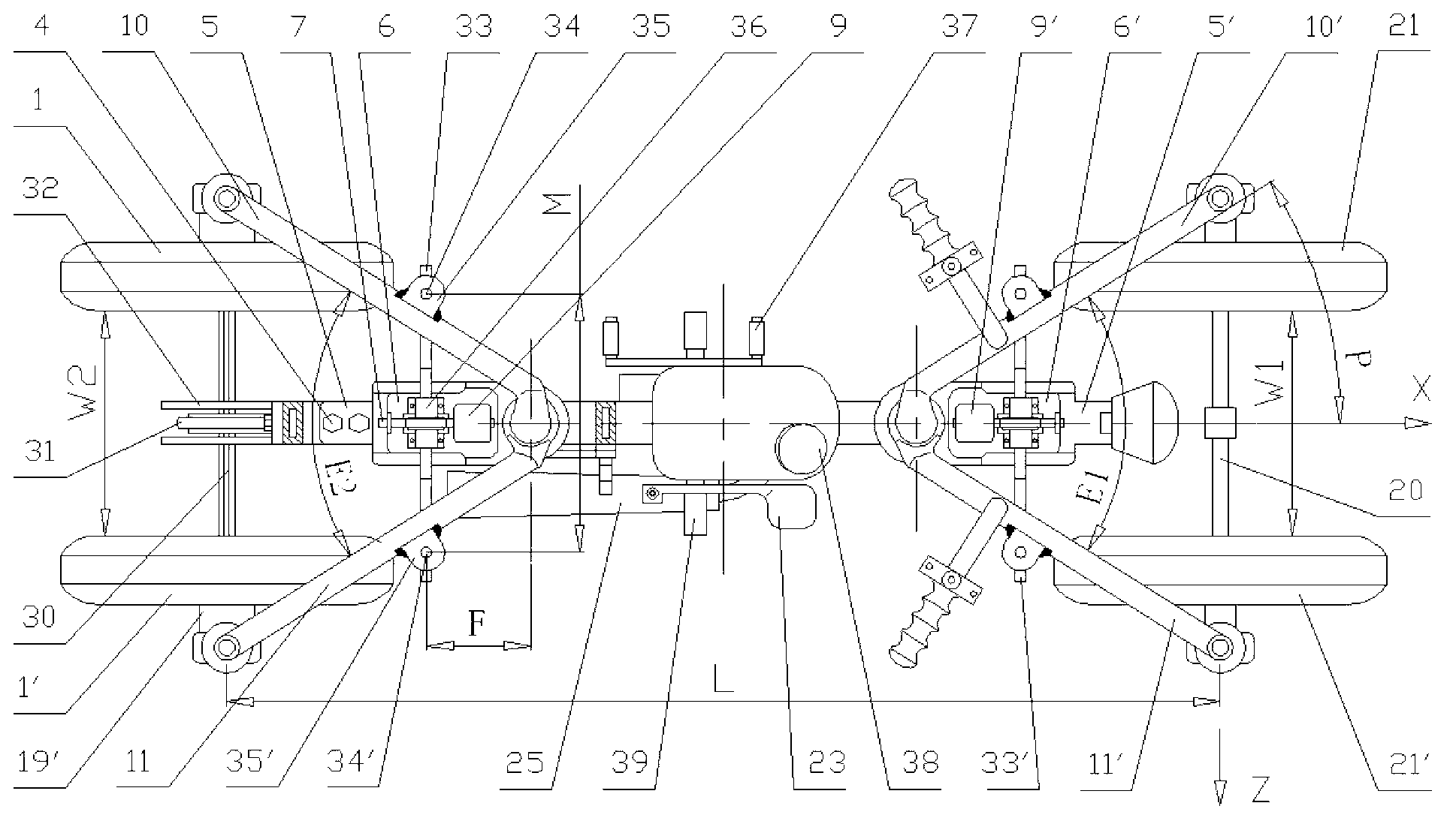
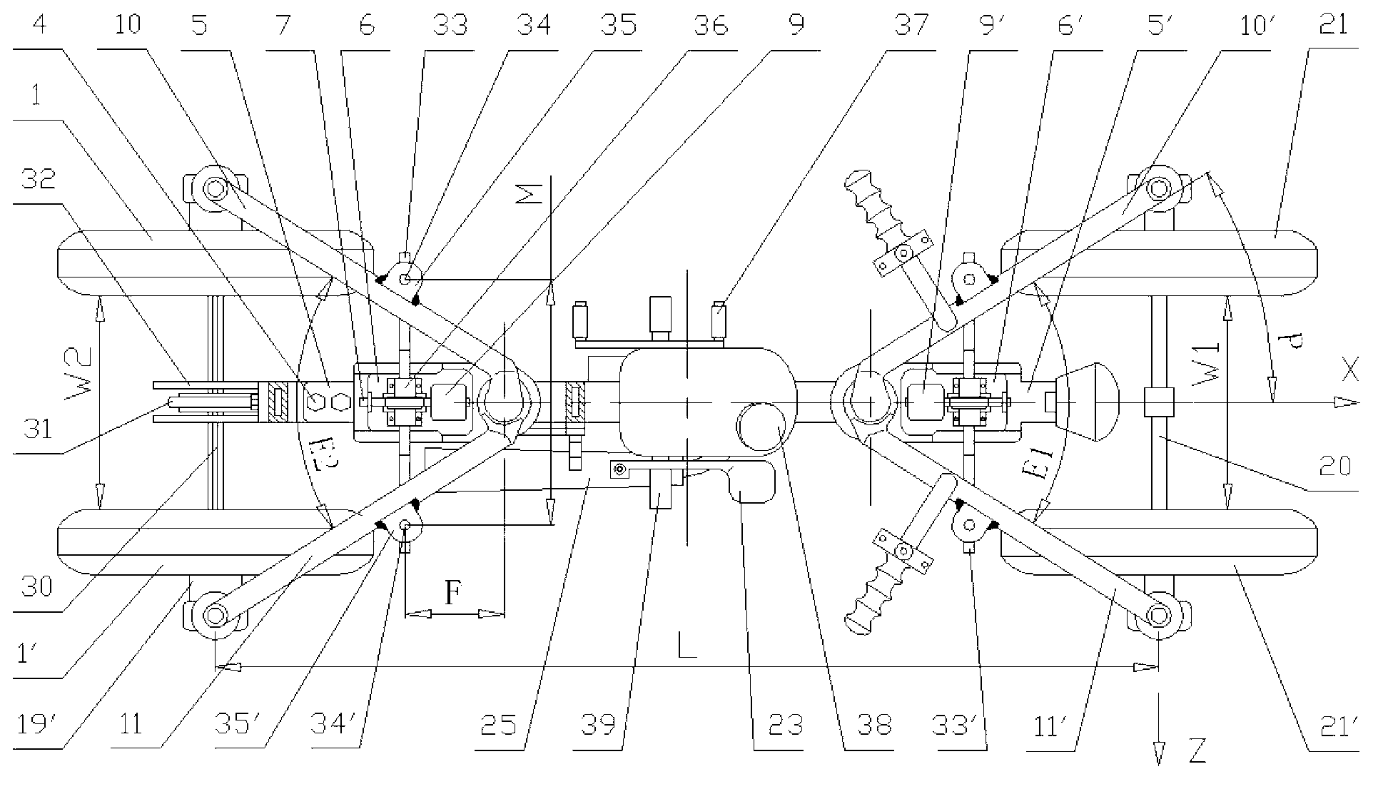
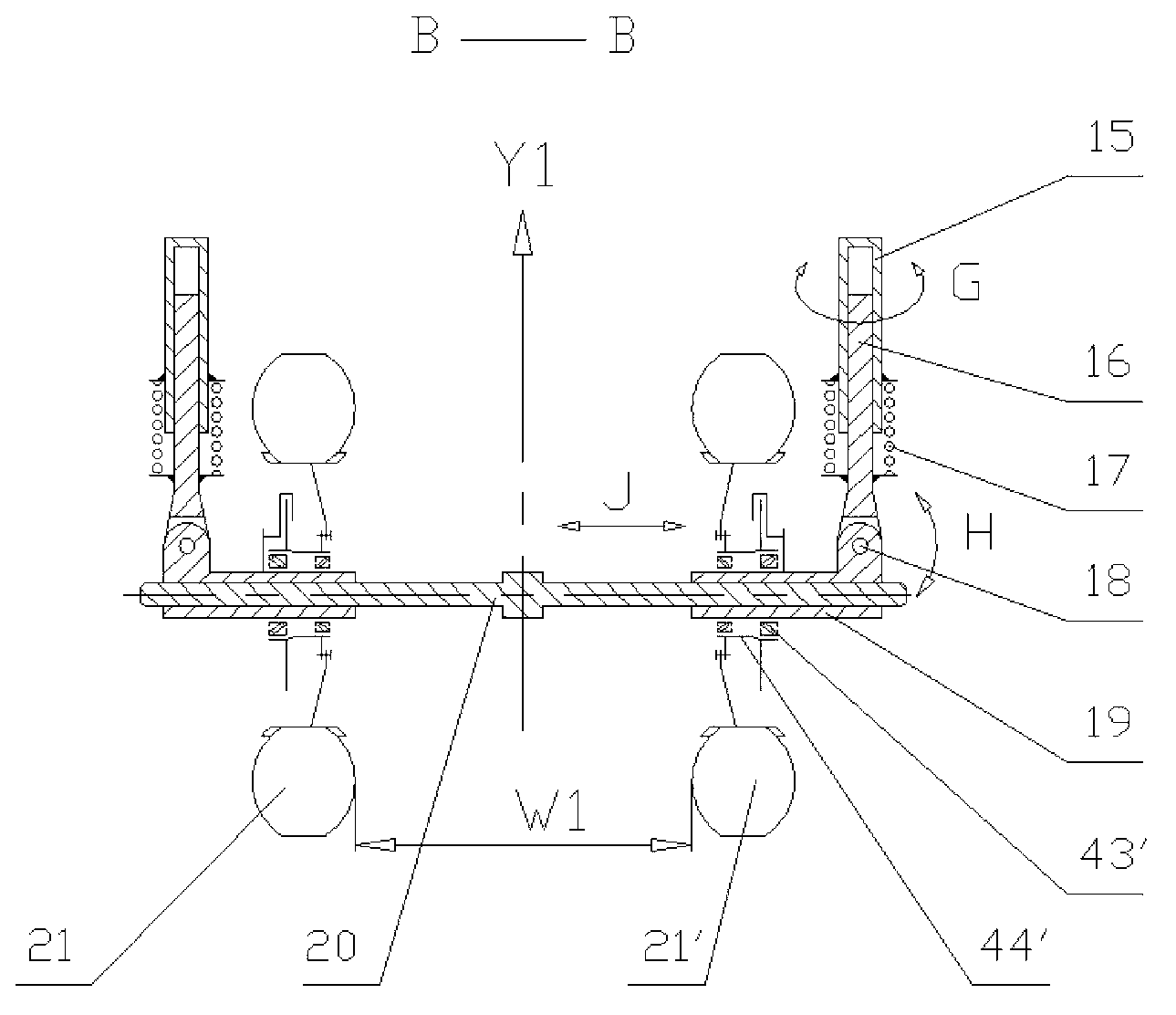
[0035] The variable split angle suspension mechanism of this embodiment is driven by the engine, handle-type direction, "n" type rotating arm, and the wheelbase adjustment mechanism is arranged upwards, combined with the accompanying drawings - 1, 2, 3, 4, 5 shows further explanation:
[0036] Rotary swing arm structure:
[0037] The variable split angle suspension mechanism is divided into front and rear parts. Two rotating arm sleeves 12', 12 are respectively welded to the two ends of the middle beam 13. The axes of the rotating arm sleeves 12', 12 are respectively located at The Y1 and Y2 axis positions, and the two Y1 and Y2 axis positions are respectively used as the rotation centers of the front and rear variable split angle suspensions. The swing centers of the two swivel arms 10', 11' constituting the suspension of the front axle are at the Y1 axis position, and the variable split angle between the swivel arms 10', 11' is E1. The swing centers of the two swivel arms ...
Embodiment 2
[0052] The difference between this embodiment and Embodiment 1 is: firstly, the front axle adopts a disk-type direction, and secondly, to adapt to the disk-type direction, the rotating arm is changed to an "N" type structure. Further explanation in conjunction with accompanying drawing-6,7,8 shows:
[0053]The use of disc steering through the gear structure makes it easy to control the steering process and reduces the labor intensity of the driver. In order to adapt to the steering wheel control method, the rotating arm adopts an "N" structure; the wheelbase adjustment mechanism adopts a downward arrangement. A steering column 50 is installed on the front beam 51, a steering wheel 49 is installed on the upper end of the steering column 50 and a driving steering gear 52 is installed on the lower end, and the gear 52 drives a chute bracket 53 with fan-shaped internal teeth to rotate to realize the steering process. Rear axle is also not used as steering bridge, and the left end...
Embodiment 3
[0056] The difference between this embodiment and Embodiment 2 is that the front support bridge is increased to be driven by a motor, the battery pack 48' is assembled on the frame 22 originally supporting the engine 24, and two wheel hub motors are connected to the outer diameter of the sliding bushing 19. The two front wheels 21, 21' are driven respectively. Further explanation in conjunction with accompanying drawing-9,10 shows:
[0057] The two hub type electric drive wheels 21, 21' are symmetrical structures. Taking the wheel 21' as an example, the armature coil 59 and the armature are connected to the hub of the wheel 21' and rotate around the sliding bushing 19 through the bearing. process reaction. One end of the armature coil 59 is connected to the positive terminal 64 via the commutator 63, the brush 62, and the wire, while the other end of the armature coil 59 is connected to the negative terminal 66, and grounded via the screw 65 to form an electrical circuit.
...
PUM
 Abstract
Description
Claims
Application Information
 - R&D
- Intellectual Property
- Life Sciences
- Materials
- Tech Scout
- Unparalleled Data Quality
- Higher Quality Content
- 60% Fewer Hallucinations
Browse by: Latest US Patents, China's latest patents, Technical Efficacy Thesaurus, Application Domain, Technology Topic, Popular Technical Reports.
© 2025 PatSnap. All rights reserved.Legal|Privacy policy|Modern Slavery Act Transparency Statement|Sitemap|About US| Contact US: help@patsnap.com


