Wheel track changing suspension mechanism of traveling machinery

A technology of variable wheelbase and suspension, which is applied to the front and rear axles of motor vehicles, the distance between the two wheels on the rear axle, and the front area, which can solve the problem of easy lateral tipping and four-wheel fixed wheelbase. Problems such as poor passing ability of motor vehicles

Inactive Publication Date: 2015-04-01
JILIN UNIV
View PDF4 Cites 0 Cited by
  • Summary
  • Abstract
  • Description
  • Claims
  • Application Information

AI Technical Summary

Problems solved by technology

[0005] The purpose of the present invention is to overcome the shortcomings of the traditional two-wheeled motor vehicle standing and easy to fall sideways, and the four-wheeled fixed-track motor vehicle has poor passing capacity, and provide a variable wheel-base suspension mechanism for walking machinery

Method used


Image

  • Wheel track changing suspension mechanism of traveling machinery
  • Wheel track changing suspension mechanism of traveling machinery
  • Wheel track changing suspension mechanism of traveling machinery

Examples


Embodiment 1

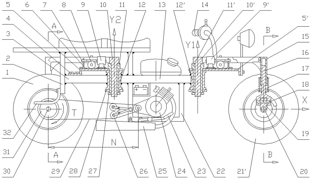
[0035] The variable split angle suspension mechanism of this embodiment is driven by the engine, handle-type direction, "n" type rotating arm, and the wheelbase adjustment mechanism is arranged upwards. figure 1 , 2 , 3, 4, 5 show further explanation:

[0036] Rotary swing arm structure:

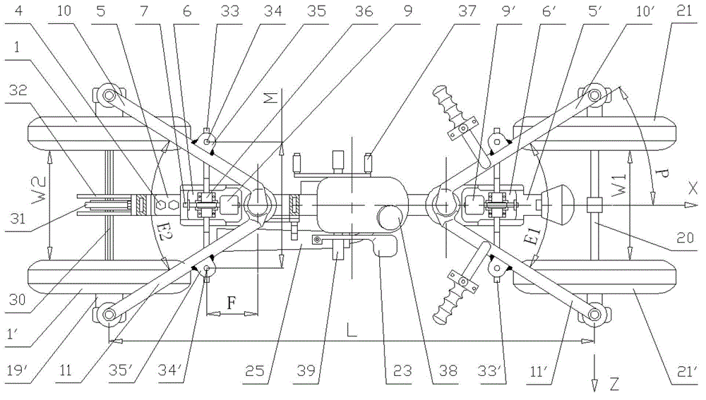
[0037] The variable split angle suspension mechanism is divided into front and rear parts. Two rotating arm sleeves 12', 12 are respectively welded to the two ends of the middle beam 13. The axes of the rotating arm sleeves 12', 12 are respectively located at The Y1 and Y2 axis positions, and the two Y1 and Y2 axis positions are respectively used as the rotation centers of the front and rear variable split angle suspensions. The swing centers of the two swivel arms 10', 11' constituting the suspension of the front axle are at the Y1 axis position, and the variable split angle between the swivel arms 10', 11' is E1. The swing centers of the two swivel arms 10 and 11 constituting the rear a...

Embodiment 2

[0052] The difference between this embodiment and Embodiment 1 is: firstly, the front axle adopts a disk-type direction, and secondly, to adapt to the disk-type direction, the rotating arm is changed to an "N" type structure. combined with Figure 6 , 7 , 8 shows further explanation:

[0053] The use of disc steering through the gear structure makes it easy to control the steering process and reduces the labor intensity of the driver. In order to adapt to the steering wheel control method, the rotating arm adopts an "N" structure; the wheelbase adjustment mechanism adopts a downward arrangement. A steering column 50 is installed on the front beam 51, a steering wheel 49 is installed on the upper end of the steering column 50 and a driving steering gear 52 is installed on the lower end, and the gear 52 drives a chute bracket 53 with fan-shaped internal teeth to rotate to realize the steering process. Rear axle is also not used as steering bridge, and the left end of chute supp...

Embodiment 3

[0056] The difference between this embodiment and Embodiment 2 is that the front support bridge is increased to be driven by a motor, the battery pack 48' is assembled on the frame 22 originally supporting the engine 24, and two wheel hub motors are connected to the outer diameter of the sliding bushing 19. The two front wheels 21, 21' are driven respectively. combined with Figure 9 , 10 Further clarification is shown:

[0057] The two hub type electric drive wheels 21, 21' are symmetrical structures. Taking the wheel 21' as an example, the armature coil 59 and the armature are connected to the hub of the wheel 21' and rotate around the sliding bushing 19 through the bearing. process reaction. One end of the armature coil 59 is connected to the positive terminal 64 via the commutator 63, the brush 62, and the wire, while the other end of the armature coil 59 is connected to the negative terminal 66, and grounded via the screw 65 to form an electrical circuit.

[0058] On...


PUM


Abstract

The invention relates to a wheel track changing suspension mechanism of traveling machinery. The wheel track changing suspension mechanism is especially suitable for changing distance between wheels on two sides on a front axle and a rear axle and distance between the front axle and the rear axle of a motor vehicle. The mechanism mainly comprises front and rear variable folio angle suspension mechanisms, front and rear wheel track adjusting mechanisms and a steering mechanism, front and rear suspensions respectively comprise left and right rotary arms in symmetric arrangement, one ends of the left and right rotary arms are hinged, the hinged end is fixed on an intermediate cross beam through a rotary arm sleeve, the other ends of the left and right rotary arms are fixedly provided with vertical shafts and vertical shaft sleeves in a sleeved manner, one ends of the vertical shafts are hinged with sliding sleeves which are respectively mounted at two ends of an optic shaft on front wheels and a spline shaft on rear wheels, the included angle between the left and right rotary arms is adjusted through the front and rear wheel track adjusting mechanisms which are structurally identical and symmetric, and the steering mechanism performs direction handle type control or direction disc type control. The wheel track changing suspension mechanism has the advantages of high trafficability, low requirements on road surface condition, stability in standing and the like.

Description

technical field [0001] The invention relates to a variable wheelbase suspension mechanism of a walking machine, which is especially suitable for motor vehicles to change the distance between two side wheels on the front and rear axles and the distance between the front and rear axles. Background technique [0002] Motorcycles have the advantages of fast and convenient use, good mobility, less fuel consumption, and low manufacturing costs, and are widely used in the world. According to statistics, the cumulative global motorcycle production has exceeded 200 million by 2008. my country has a population of 1.3 billion and is the largest developing country in the world. The per capita motor vehicle ratio is not high. With the rapid growth of the national economy, the demand for motorcycles and electric vehicles will increase, especially in urban and rural areas. widely. [0003] Traditional two-wheeled motor vehicles have the advantages of good passing ability and low requiremen...

Claims


Application Information

Patent Timeline
Patent Type & Authority Patents(China)
IPC IPC(8): B62K5/01
Inventor 方显忠
Owner JILIN UNIV
Why Eureka
Try Eureka