
Mechanical carrying device

A technology for mechanical handling and lead screw nuts, applied in the direction of transportation and packaging, conveyor objects, etc., can solve the problems of poor control of manipulator operation accuracy, high power requirements, slow activation and operation, etc., to achieve labor-saving handling and large transmission force , long service life effect

Inactive Publication Date: 2013-04-24
ZHEJIANG TONGJI VOCATIONAL COLLEGE OF SCI & TECH
View PDF8 Cites 3 Cited by
  • Summary
  • Abstract
  • Description
  • Claims
  • Application Information

AI Technical Summary

Problems solved by technology

However, most of these machines have complex structures, high power requirements, slow activation and operation, and the operation accuracy of the manipulator is not easy to control.

Method used


Image

  • Mechanical carrying device
  • Mechanical carrying device
  • Mechanical carrying device

Examples


Embodiment 1

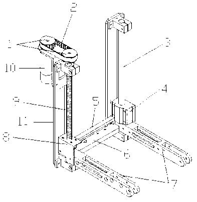
[0023] combined with figure 1 As shown, a kind of mechanical handling device comprises a support 11, a motor 10 installed on the support 11, a lead screw 9 with a lead screw nut 8 and a polished rod 3 with a slider 4 are also installed on the support 11, Screw mandrel 9 is parallel with polished rod 3, is connected by linkage rod 5 between described screw nut 8 and slide block 4, and described motor 10 and leading screw 9 are respectively provided with synchronous pulley 1 (comprising motor synchronous pulley and wire Bar synchronous pulley), synchronous belt 2 drives and connects 2 synchronous pulleys 1; Support bar 6 and arm 7 are installed on described leading screw nut 8 and slide block 4, and described arm 7 and screw mandrel 9 are perpendicular to each other.

[0024] When working, the motor 10 drives the synchronous pulley of the motor, drives the synchronous pulley of the screw rod through the transmission of the timing belt 2, and then drives the screw rod 9 to rotate...

Embodiment 2

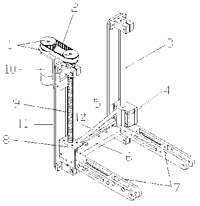
[0029] combined with image 3 As shown, a kind of mechanical handling device comprises a support 11, a motor 10 installed on the support 11, a lead screw 9 with a lead screw nut 8 and a polished rod 3 with a slider 4 are also installed on the support 11, The screw nut 8 and the slide block 4 are connected by a linkage rod 5, and the motor 10 and the leading screw 9 are respectively provided with a synchronous pulley 1, and the synchronous belt 2 is driven to connect two synchronous pulleys 1; the leading screw The nut 8 and the slide block 4 can be provided with a support rod (the linkage rod 5 on the screw nut 8 and the slide block 4 can also play the role of a support rod, and the linkage rod 5 has not only played a role of fixed installation, but also can bear cargo).

[0030] Preferably, a diagonal brace with an included angle of 60-80° to the screw rod is further provided between the lead screw nut and the slider, and the length of the corresponding slider along the dire...


PUM


Abstract

The invention relates to a mechanical carrying device for transporting articles, in particular to a mechanical carrying device which comprises a support and a motor. The motor is mounted on the support, a lead screw and a polished rod are further mounted on the support, a lead screw nut is sleeved on the lead screw, a slider is sleeved on the polished rod, the lead screw is parallel to the polished rod and is in transmission connection with the motor by a synchronous belt, the lead screw nut is connected wit the slider by a linkage lever, and a support rod is further arranged between the lead screw nut and the slider. The single lead is used for transmission, the linkage lever between the lead screw nut and the slider drives the slider on the other side of the linkage lever to move vertically, the mechanical carrying device is simple in structure and low in cost, is abrasion-resistant, and is high in transmission force, stable in movement and low in friction resistance owing to the single driving motor, and rotation is converted into linear movement. Besides, extending lengths and extending and retracting speeds of mechanical arms are adjusted by the aid of clockwise rotation and anticlockwise rotation of the motor. In addition, force generated by the lead screw nut can be effectively transmitted to the slider by a diagonal bracing, and labor can be effectively saved when the mechanical carrying device is used for carrying articles.

Description

technical field [0001] The invention relates to a mechanical handling device for article transportation, in particular to a mechanical handling device. Background technique [0002] With the advent of the era of economic globalization, flexible production, diversified consumption, and high-speed circulation, the acquisition of production materials and the expansion of product sales, production, material circulation, commodity exchange and management methods have undergone profound changes. Variety. This has also brought about the rapid development of the modern logistics industry around the world. Logistics Equipment. In order to meet the needs of employees in transportation, ports, airports and industrial and mining enterprises, so that they can easily familiarize and master the structure, principle, use, maintenance, development of existing forklifts, as well as daily maintenance measures and forklift repair and improvement requirements, And make reasonable selection t...

Claims


Application Information

Patent Timeline
Patent Type & Authority Applications(China)
IPC IPC(8): B65G47/74
Inventor 廖君单澜方寒涛章海涛葛佳宇
Owner ZHEJIANG TONGJI VOCATIONAL COLLEGE OF SCI & TECH
Learn More