Grouting pipe

A technology of grouting pipes and nozzles, which is applied in the field of building construction, can solve the problems of slow grouting speed and uneven diffusion of grouting fluid, and achieve the effects of fast grouting speed, improved construction quality, and convenient manufacture

Active Publication Date: 2013-04-24
浙江环宇建设集团有限公司
View PDF7 Cites 6 Cited by
  • Summary
  • Abstract
  • Description
  • Claims
  • Application Information

AI Technical Summary

Problems solved by technology

The grouting pipe of the present invention can solve the problems of slow grouting speed and uneven diffusion of grout, and at the same time has a simple structure and is convenient to manufacture

Method used


Image

  • Grouting pipe
  • Grouting pipe

Examples


Embodiment Construction

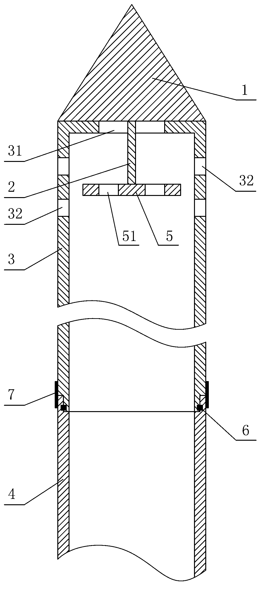
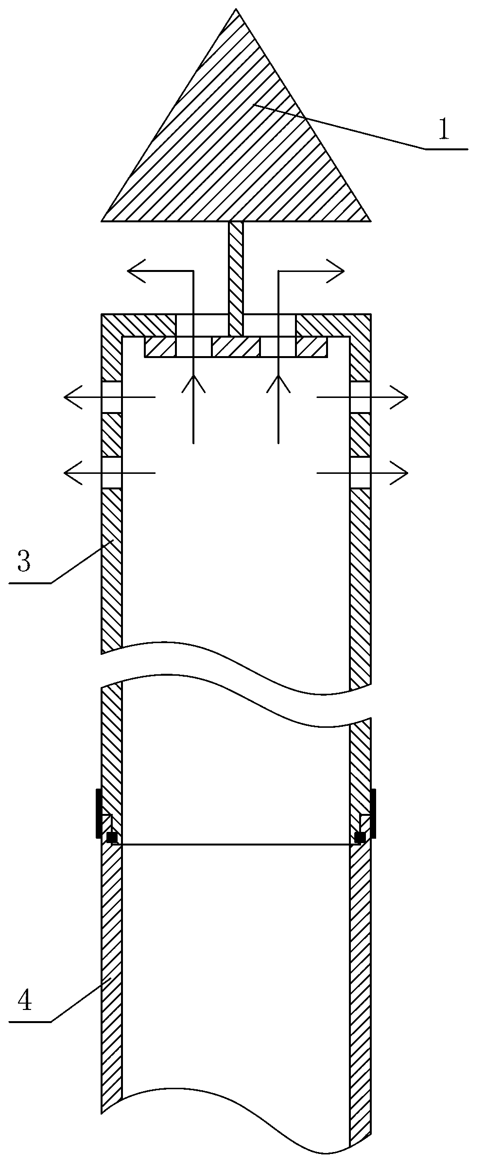
[0013] Such as figure 1 As shown, the grouting pipe of the present invention includes a tapered plug 1, a connecting rod 2, and a grouting pipe body 3 connected in sequence. One end of the connecting rod 2 is fixedly connected with the tapered plug 1, and the other end extends from the nozzle 31 of the grouting pipe body 3 into the grouting pipe body 3, and is fixedly arranged on the end of the connecting rod 2 in the grouting pipe body 3 There is a chuck 5, which is movably clamped in the nozzle 31 (that is, the chuck 5 is movably located in the grouting pipe body 3, but cannot be separated from the grouting pipe body 3 through the nozzle 31), on the chuck 5 A plurality of uniformly distributed through holes 51 are opened, and each of the through holes 51 is connected with the nozzle 31; the pipe wall of the grouting pipe body 3 is provided with a plurality of uniformly distributed through holes 32.

[0014] When the length of the grouting pipe body 3 is insufficient, the end of...


PUM


Abstract

The invention discloses a grouting pipe and belongs to the technical field of building construction. The grouting pipe comprises a tapered plug, a connecting rod and a grouting pipe body which are sequentially connected, one end of the connecting rod is fixedly connected with the tapered plug, the other end of the connecting pipe extends into the grouting pipe body from a pipe orifice of the grouting pipe body, a chuck is fixedly arranged at the tail end of the connecting rod located in the grouting pipe body and movably clamped in the pipe orifice, a plurality of first through holes are reserved on the chuck and are all communicated with the pipe orifice, and a plurality of second through holes are reserved on the pipe wall of the grouting pipe body. The grouting pipe is capable of solving the problems of low grouting speed and slurry diffusion nonuniformity, and is simple in structure and convenient to manufacture.

Description

Technical field [0001] The invention discloses a grouting pipe, which belongs to the technical field of building construction. Background technique [0002] In the process of building construction, when strengthening some sections or soft soil layers that are prone to collapse, grouting pipes are generally used to inject grout into the corresponding sections or soil layers for reinforcement. During construction, drill holes at the designated grouting position, and then insert the grouting pipe into the hole for grouting. With the continuous improvement of construction requirements, the grouting pipe of the existing structure has become less and less able to meet its requirements, which is mainly reflected in the following two points: the grouting speed is slow and the grout spreads unevenly. At the same time, because the length of the grouting pipe of the existing structure is designed in advance, when grouting in some special areas, the length of the grouting pipe will be insuf...

Claims


Application Information

Patent Timeline
Patent Type & Authority Applications(China)
IPC IPC(8): E02D15/04
Inventor 金关峰范家海刘文革史久其童宏伟陈玉燕
Owner 浙江环宇建设集团有限公司
Why Eureka
Try Eureka