Slurry filling device for tunnel pipe

A grouting device and tunnel technology, applied in tunnels, tunnel linings, shaft equipment and other directions, can solve the problems of potential safety hazards, low work efficiency, troublesome removal, etc. Good effect of slurry reinforcement

Active Publication Date: 2013-04-24
中铁二十二局集团第四工程有限公司 +2
View PDF8 Cites 3 Cited by
  • Summary
  • Abstract
  • Description
  • Claims
  • Application Information

AI Technical Summary

Problems solved by technology

The disadvantages of this approach are: ①. The high-pressure grouting pipe and the pipe wall cannot be completely tightly connected, resulting in grout leakage, accidents such as pipe detachment and injury; ②. The grouting reaches the design required pressure and injection After the amount of grout is not solidified, if the high-pressure grouting pipe is removed too early, the grout will be lost; if it is too late, the grout will solidify, the high-pressure grouting pipe will be blocked, it will be troublesome to remove, and it will be difficult to clean
The disadvantages of this method are: if rubber hoses are used for tying with iron wires, it is also easy to leak slurry and the operation is troublesome; the problem of slurry leakage can be solved by using welding connection, but welding is very troublesome, and additional sections need to be cut later, in narrow tunnels In the working area, the work efficiency is very low, many sets of personnel and equipment need to be invested, and there are potential safety hazards

Method used


Image

  • Slurry filling device for tunnel pipe
  • Slurry filling device for tunnel pipe
  • Slurry filling device for tunnel pipe

Examples


Embodiment Construction

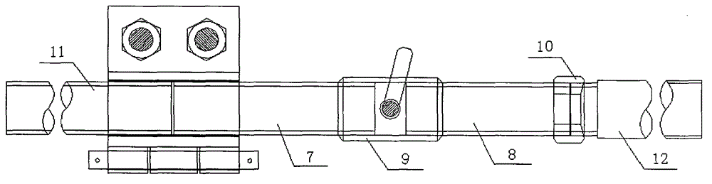
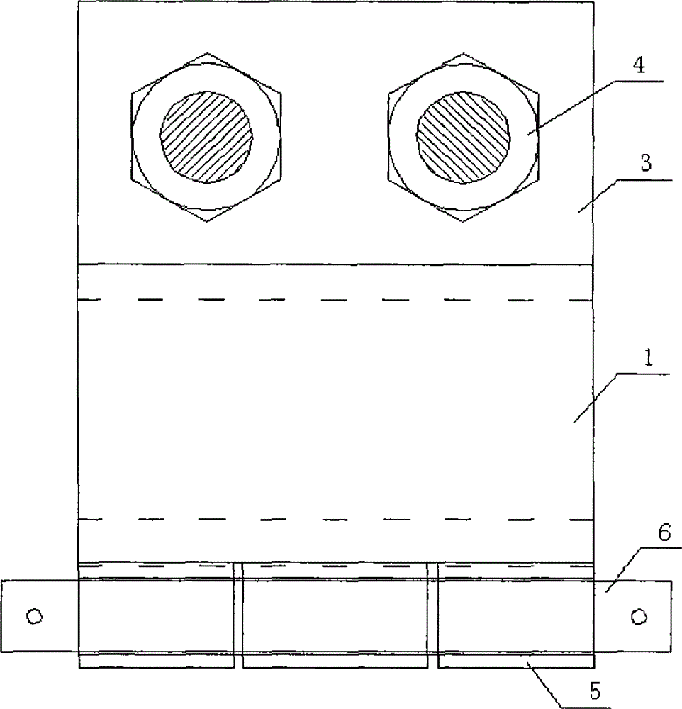
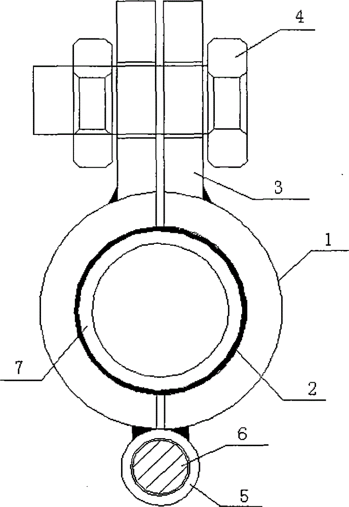
[0019] Figure 1-3 As shown, a tunnel conduit grouting device, including a tunnel grouting conduit, is characterized in that: it also includes a grouting device and a connecting device; the grouting device is composed of a round joint, a fixing piece, a sealing ring and a loose-leaf mechanism, The circular connecting pipe is composed of two semicircular pipes, a sealing ring is set in the circular connecting pipe, one end of the circular connecting pipe is connected to the tunnel grouting conduit, and the other end is connected to a connecting device communicated with the grouting pump, and the outer wall of the circular connecting pipe is connected with a The fixing piece for fastening the round joint and the loose-leaf mechanism for opening and closing the round joint, the fixing piece and the loose-leaf mechanism are arranged oppositely.

[0020] The circular connecting pipe is made of a steel pipe, which is cut and divided into two halves, and each section is ground off by...


PUM


Abstract

The invention discloses a slurry filling device for a tunnel pipe. The slurry filling device comprises a slurry filling pipe of a tunnel and is characterized by further comprising a slurry pressing device and a connection device. The slurry pressing device is composed of a round connection pipe, a fixing member, a sealing ring and a hinge mechanism, wherein the round connection pipe is composed of two semi-round pipes, the sealing ring is arranged in the round connection pipe, one end of the round connection pipe is connected with the slurry filling pipe of the tunnel, the other end of the round connection pipe is connected with the connection device communicated with a slurry filling pump, and the fixing member for fastening the round connection pipe and the hinge mechanism for opening and closing the round connection pipe are connected onto the outer wall of the round connection pipe, and the fixing member and the hinge mechanism are oppositely arranged. The slurry filling device ensures that the slurry cannot be leaked during filling, simultaneously can achieve continuous and intermittent slurry filling, is good in slurry filling reinforcing effect, greatly reduces the cycling time of slurry filling operation, is high in working efficiency, simultaneously shortens the time for slurry filling of surrounding rocks, is easy and convenient to operate, does not need welding operation at site, performs binding reinforcing operation through iron wires manually, is low in labor intensity and easy to process and manufacture, can be utilized fully and repeatedly and saves materials.

Description

technical field [0001] The invention relates to the technical field of building engineering construction; in particular, it relates to a tunnel conduit grouting device. Background technique [0002] In tunnel construction, in order to advance the reinforcement of the surrounding rock of the tunnel, many designs use advanced conduits for grouting reinforcement. That is to take the first drilling, after loading the conduit, connect the grouting equipment at the end of the conduit for grouting reinforcement. The grouting connection at the end of the conduit is a key part, which directly determines the quality of the grouting effect. [0003] The traditional method is as follows: one method is: after the pipe is drilled and the gap between the pipe wall and the hole is blocked, the high-pressure grouting pipe is directly connected to the tail of the pipe, and the grouting pipe and the pipe are fixed and sealed with iron wires. , start the grouting operation. The disadvantages...

Claims


Application Information

Patent Timeline
Patent Type & Authority Applications(China)
IPC IPC(8): E21D11/10
Inventor 白子斌邓寿军周仁波张育红
Owner 中铁二十二局集团第四工程有限公司
Why Eureka
Try Eureka