Copper conductor welding machine and welding technology thereof

A technology of copper wire and welding machine, applied in the direction of welding/welding/cutting items, welding equipment, welding equipment, etc., can solve the problems of false welding and false welding, and achieve the effect of simple and convenient operation, high efficiency and light weight

Pending Publication Date: 2018-09-18
夏朝纲
View PDF0 Cites 2 Cited by
  • Summary
  • Abstract
  • Description
  • Claims
  • Application Information

AI Technical Summary

Problems solved by technology

[0005] The purpose of the present invention is to provide a copper wire welding machine with reasonable structure and reliable use and its welding process, which fundamentally solves the problems of false welding and virtual welding existing in existing welding devices, and does not require the use of flux to improve the welding effect. Good, high mechanical strength, no arc light and spark leakage during welding, significantly improving operation safety

Method used


Image

  • Copper conductor welding machine and welding technology thereof
  • Copper conductor welding machine and welding technology thereof
  • Copper conductor welding machine and welding technology thereof

Examples


Embodiment Construction

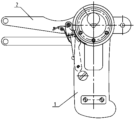
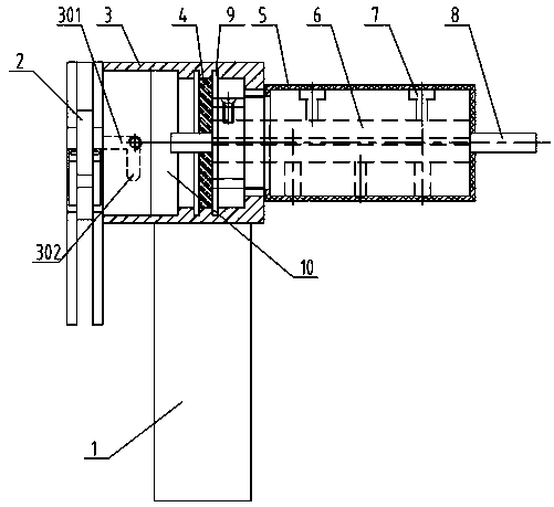
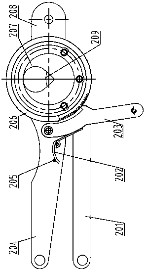
[0036] Such as Figure 1-Figure 7 As shown, the copper wire welding machine includes welding clamps and an electrical control system.

[0037] Wherein, the welding pliers includes a handle part 1, an outer cover 3 connected to the top of the handle part 1, a clamping part 2 connected to one end of the outer cover 3, an insulating sleeve 5 connected to the other end of the outer cover 3, and a Carbon rod clamp 6, the slip ring 4 which is arranged in the outer cover 3 and has a carbon rod insertion hole in the middle; the clamping part 2 includes front and rear ratchets 206, 212, and clamped front and rear ratchets 206, The dynamic and constant pressure rods 204, 201 between 212, the ratchet 203 that is hinged on the side of the dynamic pressure rod 204 and the ratchet, the torsion spring assembly that is used to drive the ratchet 203 on the side of the dynamic pressure rod 204, and the front The front end of the ratchet wheel 206 is connected to the fixed cylindrical joint 210...


PUM


Abstract

The invention relates to a copper conductor welding machine and a welding technology thereof. A welding plier and an electric control system are included, and the copper conductor welding machine andthe welding technology are characterized in that the welding plier comprises a handle part, a jacket, a clamping part, an insulating sleeve, a carbon rod clamp and a sliding ring; the clamping part comprises front and back ratchet wheels, movable and fixed pressing rods, a pawl hinged to the side face of the movable pressing rod and matched with the ratchet wheels, a torsional spring assembly arranged on the side face of the movable pressing rod and used for driving the pawl and a barrel-shaped connector connected with the front end face of the front ratchet wheel; and the handle part comprises an insulating shell, an electric brush arranged in the insulating shell and matched with the sliding ring and an electric conduction connecting rod connected with the lower end face of the electricbrush, a cable is inserted into the bottom of the insulating shell, the end of the cable is connected with the electric conduction connecting rod, and the other end of the cable is connected with a direct-current output circuit of the electric control system. The copper conductor welding machine and the welding technology fundamentally solve the problems about cold solder and dry joint of an existing welding device, scaling powder does not need to be used, the welding effect is good, the mechanical strength is high, arc light and spark leakage can be avoided during welding, and the operation safety is obviously improved.

Description

technical field [0001] The invention relates to a copper wire welding device, in particular to a small copper wire welding machine and its welding process. Background technique [0002] At present, there is no dedicated copper wire welding device on the market. Specifically, there is no welding device designed for copper wire joints in buildings and other constructions and home improvement fields. Existing copper wire joints usually use wire cutters to twist or twist the wires. Solder with a soldering iron or tin pot after winding together. [0003] This method has the following problems: 1. Before the wires are spliced, the wires need to be cleaned (remove the oxide layer, etc.) before welding, otherwise false welding will be caused, the use is unreliable, and repeated operations are required, which is time-consuming and laborious; 2. Soldering Sometimes flux is needed, and some operators use acidic flux, which has a corrosive effect on the wire; 3. False welding or virtua...

Claims


Application Information

Patent Timeline
Patent Type & Authority Applications(China)
IPC IPC(8): B23K9/28B23K9/32B23K9/10B23K28/02B23K37/04B23K101/32B23K101/38
CPCB23K9/28B23K9/10B23K9/32B23K28/02B23K37/04B23K37/0443
Inventor 夏朝纲
Owner 夏朝纲
Why Eureka
Try Eureka