Two-stroke aerodynamic engine assembly

An engine assembly and aerodynamic technology, applied in the direction of engines, engine components, combined engines, etc. based on the principle of one-way flow

Active Publication Date: 2013-04-24
周登荣 +1
View PDF10 Cites 45 Cited by
  • Summary
  • Abstract
  • Description
  • Claims
  • Application Information

AI Technical Summary

Problems solved by technology

[0012] Based on the above problems, the present invention provides a two-stroke aerodynamic engine, which aims to solve the problem of effective work of the compression engine, thereby realizing an economical, high-efficiency, zero-emission new aerodynamic engine

Method used

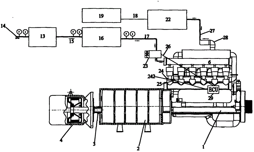
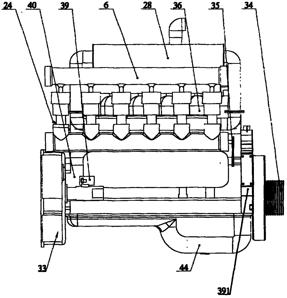
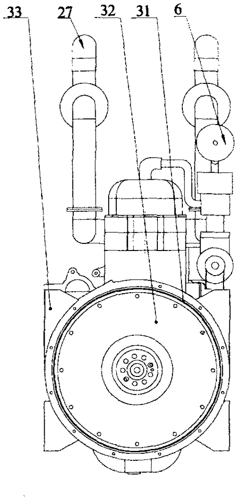

Image

  • Two-stroke aerodynamic engine assembly
  • Two-stroke aerodynamic engine assembly
  • Two-stroke aerodynamic engine assembly

Examples


Embodiment Construction

[0050] The following description is merely exemplary in nature and not intended to limit the disclosure, application or use. It should be understood that throughout the drawings, corresponding reference numerals indicate like or corresponding parts and features.

[0051] Before describing the specific embodiment of the present invention in detail, earlier carry out theoretical analysis with regard to the energy of aerodynamic engine.

[0052] The work process of an aerodynamic engine is relatively simple, only the process of compressing air to expand and do work. Such as Figure 12A as shown, Figure 1-5 It is the isothermal expansion process of compressed air, and 1-6 is the adiabatic expansion process of compressed air. The work done by compressed air in the engine cannot be a complete isothermal process, usually between the isothermal process and the adiabatic process. In order to improve the energy utilization rate of compressed air, a multi-stage adiabatic process can ...


PUM


Abstract

The invention relates to a two-stroke engine, in particular to a two-stroke aerodynamic engine assembly which takes compressed air as a power source. The two-stroke aerodynamic engine assembly comprises an engine body (1), a multicolumn power distributor (2), a power device (3), a controller system (6), an air inlet control compensated flow control valve (23), a high-pressure air tank set (13), a constant-pressure tank (16) and an electric control unit (ECU) (29).

Description

technical field [0001] The invention relates to a two-stroke engine, in particular to a two-stroke aerodynamic engine assembly using compressed air as a power source. Background technique [0002] Engines are widely used in all walks of life. In modern transportation tools such as automobiles and ships, piston-type internal combustion engines that use fuel as a power source are generally used. On the one hand, this kind of engine using fuel oil as the power source pollutes the environment due to insufficient fuel combustion, so that the discharged gas contains a large amount of harmful substances and pollutes the environment. The shortage makes the development and utilization of fuel engines more and more restricted. Therefore, developing new, clean, non-polluting alternative energy sources, or reducing fuel consumption and emissions as much as possible has become an urgent problem in engine development. To this end, countries have gone through complex and arduous explorat...

Claims


Application Information

Patent Timeline
Patent Type & Authority Applications(China)
IPC IPC(8): F01B25/02F01B25/12F01B1/06F01B21/04F16C3/06
CPCF01B23/10F03G7/00F01B17/025F01B23/00F02B75/02F02B2075/025F01B25/02F01B29/04
Inventor 周登荣周剑
Owner 周登荣
Why Eureka
Try Eureka