Hydraulic combined oscillating floater wave energy generation device

A power generation device and combined technology, which is applied in ocean energy power generation, engine components, machines/engines, etc., can solve the problems of short wave energy cycle, high energy flow density, and low utilization rate, and achieve high wave energy utilization rate , Improve the energy conversion rate, the effect of less energy conversion times

Active Publication Date: 2013-04-24
OCEAN UNIV OF CHINA
View PDF10 Cites 13 Cited by
  • Summary
  • Abstract
  • Description
  • Claims
  • Application Information

AI Technical Summary

Problems solved by technology

[0006] Compared with the high wave height and high energy flow density in the coastal waters of European and American countries, the wave energy cycle in the coastal waters of my country is short, the wave height is small, and the availability rate is low, which is not suitable for the above two methods

Method used


Image

  • Hydraulic combined oscillating floater wave energy generation device
  • Hydraulic combined oscillating floater wave energy generation device
  • Hydraulic combined oscillating floater wave energy generation device

Examples


Embodiment 1

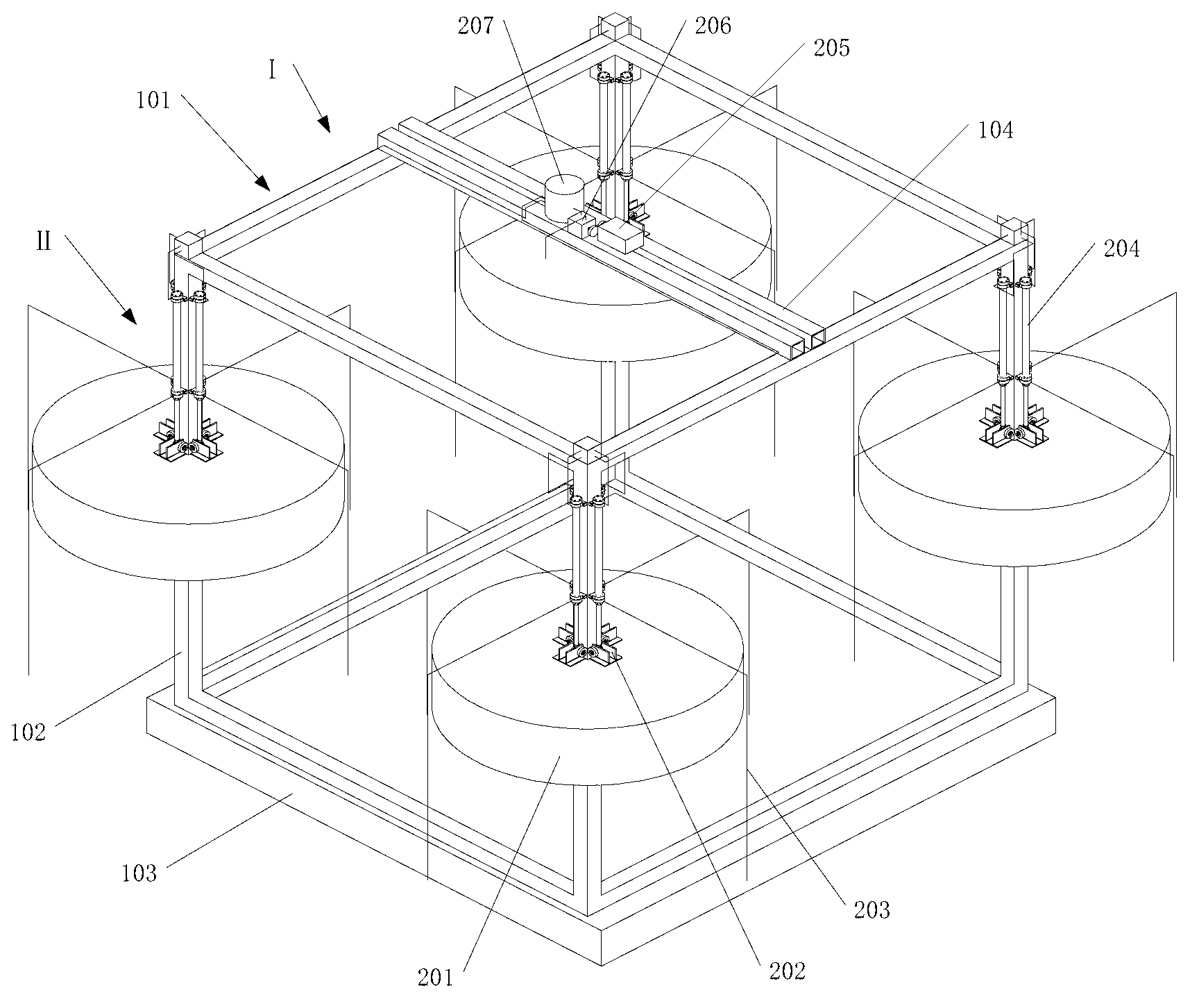
[0028] Such as Figure 1-Figure 4 Shown: the present invention includes power generation system II and fixed system I.

[0029] Among them, the fixed system I includes a floating tank 103 and a fixed frame 101. The fixed frame 101 is a cube structure, which is fixedly connected to the top of the floating tank 103. The top of the fixed frame 101 is provided with a beam 104. The four corners of the fixed frame 101 are respectively provided with columns 102 and 102 For the quadrangular prism structure.

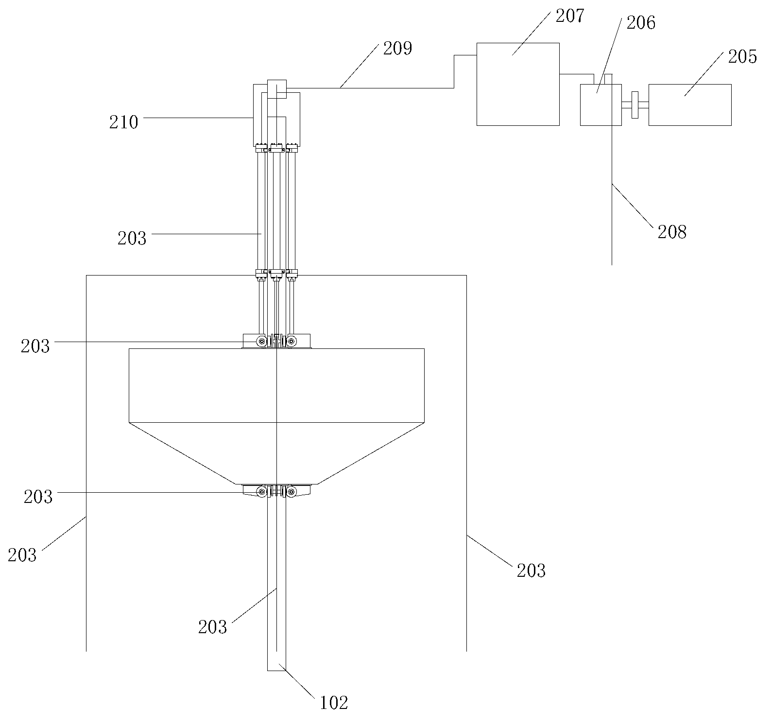
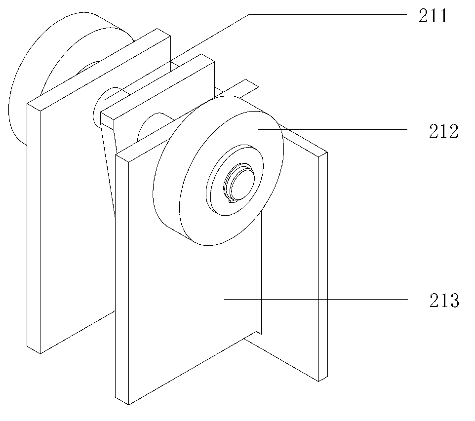
[0030] The power generation system II includes a float 201, an energy conversion device and an energy output device. The four columns 102 are respectively fitted with floats 201 , and the floats 201 move up and down along the columns 102 . The top and bottom of each float 201 are provided with four identical guiding devices 202 for limiting the movement of the float 201 in the horizontal direction. The guiding device 202 can eliminate the influence of waves on the horizontal o...

Embodiment 2

[0036] Except following difference, other is with embodiment 1.

[0037]The buoyancy tank 103 is a hollow structure, which can be filled with appropriate amount of seawater or sand for counterweight according to the sea conditions, so that the entire power generation device can sink to a certain depth below the water surface, and the float 201 can vibrate up and down at a suitable position, while ensuring The stability of the power generation plant as a whole during operation. The fixed system I has a simple structure and flexible counterweight, which improves the stability and reliability of the entire power generation device, facilitates processing and implementation, and is economical.

[0038] The buoy box 103 provides a downward pulling force through its own weight and the counterweight of the sand in the box, so that the entire power generation device can be immersed in a certain depth of the seabed, so that the float 201 makes normal reciprocating vibrations up and down...

Embodiment 3

[0040] Except following difference, other is with embodiment 1.

[0041] Such as Figure 5 As shown, the float 201 is a hollow cylinder with an inverted conical bottom. The structure of the buoy 201 is conducive to collecting more wave energy, and its inner hollow can be loaded with counterweight according to sea conditions. The surface layer of the float 201 is coated with anti-corrosion paint to prevent corrosion by seawater.


PUM


Abstract

The invention relates to a hydraulic combined oscillating floater wave energy generation device. The hydraulic combined oscillating float wave energy generation device comprises a power generation system and a fixed system. The fixed system comprises a floating box and a fixed frame, wherein the fixed frame has a cube structure, and is fixedly connected with the top of the floating box; a cross beam is arranged on the top of the fixed frame; and quadrangular upright columns are respectively arranged at four corners on the side surface of the fixed frame. The power generation system includes a floater, an energy conversion device and an energy output device, wherein the floater is sheathed on the upright columns of the fixed frame; four identical guide devices for limiting horizontal movement of the floater are respectively arranged on the top and the bottom of the floater; the energy conversion device includes a mixing tank, a hydraulic motor, and four groups of identical hydraulic transmission mechanisms respectively arranged on the four upright columns at four corners on the side surface of the fixed frame; the mixing tank and the hydraulic motor are arranged on the crossbeam of the fixed frame; and the hydraulic transmission mechanism includes a hydraulic cylinder, a water inlet pipe, and water transmission pipes (A and B). The hydraulic combined oscillating floater wave energy generation device provided by the invention has the advantages of high energy conversion efficiency, high reliability, low construction cost, stable power output, and wide application.

Description

technical field [0001] The invention belongs to the technical field of wave energy power generation, in particular to a hydraulic combined type oscillating float wave energy power generation device. Background technique [0002] When a wave energy generating device performs wave energy power generation, it usually includes two energy conversion processes: first, the wave energy is converted into a form of mechanical energy that can be used by the generator, that is, a conversion process of energy; secondly, the mechanical energy is converted by the generator Output for electrical energy, that is, the secondary conversion process of energy. The core problem of the wave energy conversion device is the primary conversion process of energy. The form of mechanical energy generated by wave energy in the first conversion process is directly converted into mechanical motion by using the up and down movement of waves; some uses the up and down movement of waves to generate airflow o...

Claims


Application Information

Patent Timeline
Patent Type & Authority Applications(China)
IPC IPC(8): F03B13/22
CPCY02E10/38Y02E10/30
Inventor 史宏达刘臻马哲曹飞飞曲娜王金龙高人杰薛坤
Owner OCEAN UNIV OF CHINA
Why Eureka
Try Eureka