Screw rod type dry vacuum pump with combined screw rod rotor

A dry vacuum pump, combined technology, applied in the direction of rotary piston type/swing piston type pump parts, rotary piston type pumps, parts of pumping devices for elastic fluids, etc. The problems of high product rate and high production cost can achieve the effect of reducing the degree of dependence, good cost performance, and improving the yield

Active Publication Date: 2013-04-24
SHENYANG SCI INSTR RES CENT CHINESE ACAD OF SCI
View PDF7 Cites 10 Cited by
  • Summary
  • Abstract
  • Description
  • Claims
  • Application Information

AI Technical Summary

Problems solved by technology

However, the processing of the variable-pitch rotor profile requires the use of special fixtures or machining centers, and the detection and assembly are also relatively complicated. The defective rate in mass production is high, and the production cost is high.

Method used


Image

  • Screw rod type dry vacuum pump with combined screw rod rotor
  • Screw rod type dry vacuum pump with combined screw rod rotor
  • Screw rod type dry vacuum pump with combined screw rod rotor

Examples


Embodiment 1

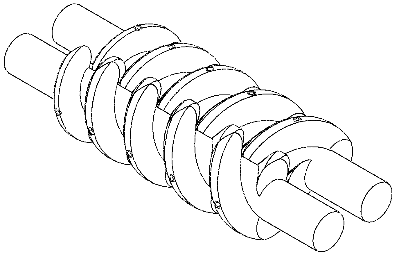
[0109] Embodiment 1 (dry vacuum pump with equal-pitch hollow screw rotor shaft in the form of double-screw connection)

[0110] Such as Figure 17 , Figure 18 As shown, the dry vacuum pump includes a driving motor 6, a pump body and a combined screw rotor. There is an air suction port 1 on the pump body, and an exhaust port 5 on the coupling frame 10. One end of the pump body is fixedly connected to the left end The other end of the cover 28 is firmly connected to one end of the coupling frame 10, and the other end of the coupling frame 10 is fixedly connected to the bearing housing 8 and the connecting end plate 7 in turn; the combined screw rotor includes the active screw rotor and the driven screw rotor. The two ends are rotated and installed on the pump body through bearings 21 respectively. One end of the driving screw rotor is connected to the output shaft of the driving motor 6 through the coupling assembly 11. The driving screw rotor and the driven screw rotor are co...

Embodiment 2

[0112] Embodiment 2 (dry vacuum pump with variable-pitch hollow screw rotor shaft in the form of double-screw connection)

[0113] The difference between this embodiment and Embodiment 1 is that both the active screw rotor and the driven screw rotor are connected by a plurality of variable-pitch hollow screw-type rotor pieces 37 and the central shaft 36, and the active screw rotor and the driven screw rotor are connected by hollow screw rotors. The pitch of the rotor blades decreases sequentially along the airflow direction.

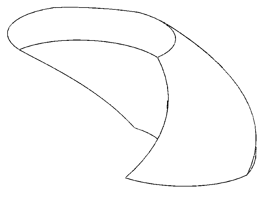
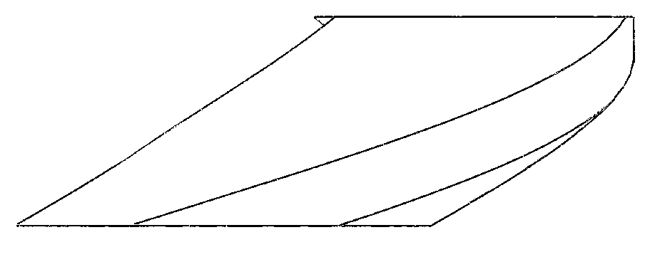
[0114] Active screw rotor such as Figure 19A As shown, it is a left-handed combined rotor shaft 24, and the driven screw rotor is as follows Figure 19B As shown, it is a right-handed combined rotor shaft 25; the two rotor shafts are formed by connecting a plurality of hollow screw rotor blades 37 with a helix angle of 180° and a central shaft 36 with variable pitch, and each rotor shaft is formed by a screw with two ends. Composition, the hollow scre...

Embodiment 3

[0116] Embodiment 3 (a dry vacuum pump with an equal-pitch hollow screw rotor shaft in the form of a screw passing through the through hole of the central shaft and bolted connections at both ends)

[0117] The difference between this embodiment and Embodiment 1 is that the central shaft 36 is evenly distributed with a plurality of connecting holes 13 in the axial direction, each connecting hole 13 is a radial through hole, and a hollow positioning hole is installed in each connecting hole 13. Pin 4, each hollow positioning pin 4 is inserted with a threaded screw 3 at both ends, and both ends of the screw 3 are fixed with hollow screw rotor pieces 37 through fastening bolts and lock washers 2 .

[0118] Active screw rotor such as Figure 25B As shown, it is a left-handed combined rotor shaft 24, and the driven screw rotor is as follows Figure 25AAs shown, it is a right-handed combined rotor shaft 25; the two rotor shafts are formed by connecting a plurality of hollow screw r...


PUM


Abstract

The invention relates to a screw rod type dry vacuum pump, in particular to a screw rod type dry vacuum pump with a combined screw rod rotor, which comprises a drive motor, a pump body and a combined screw rod rotor, wherein the combined screw rod rotor comprises a drive screw rod rotor and a driven screw rod rotor; each screw rod rotor comprises a center shaft and a plurality of screw rod-shaped hollow screw rod type rotor sheets; a center hole is formed on each hollow screw rod type rotor sheet; a connecting hole is formed on the center shaft; and all the hollow screw rod type rotor sheets are positioned with the center shafts through hollow positioning pins and are connected with the center shafts through bolts or screw rods passing through the hollow positioning pins to form the combined screw rod rotor with good interchangeability. The screw rod type dry vacuum pump has the benefits that through the matching of a plurality of sections of hollow screw rod type rotor sheets, a screw pitch-equal screw rod vacuum pump and a screw pitch-variable screw rod vacuum pump can be formed; and the screw rod type dry vacuum pump can combine the advantages of the screw pitch-equal screw rod vacuum pump and the screw pitch-variable screw rod vacuum pump, facilitates the enrichment of product types and the reduction of manufacturing expenses and has a wide market application prospect.

Description

technical field [0001] The invention relates to a dry screw vacuum pump, in particular to a screw dry vacuum pump with a combined screw rotor. Background technique [0002] In recent years, with the large-scale rise of emerging strategic industries such as semiconductor electronics, photovoltaics, liquid crystal display, semiconductor lighting, and solar photovoltaics, the demand for vacuum pumps in various industries has further increased, and the global dry pump manufacturing industry has developed rapidly. The demand for dry vacuum pumps at home and abroad is increasing and the requirements are getting higher and higher. The vacuum pump manufacturing industry is facing huge challenges and opportunities. The original various types of dry vacuum pumps have their own application limitations due to their different advantages and disadvantages. [0003] Many vacuum manufacturers produce different forms of dry pumps according to the needs of different occasions. For example, t...

Claims


Application Information

Patent Timeline
Patent Type & Authority Applications(China)
IPC IPC(8): F04C25/02F04C18/16
CPCF04C2220/10F04C29/00F04C2240/70F04C18/16F01C21/08F04C2230/60F04C18/084F04C2230/85
Inventor 雷震霖王光玉刘坤张晓玉
Owner SHENYANG SCI INSTR RES CENT CHINESE ACAD OF SCI
Why Eureka
Try Eureka