Stroke-variable elastic continuously-variable transmission or rotary speed controller
A speed controller, continuously variable transmission technology, applied in belts/chains/gears, mechanical equipment, transmission devices, etc. The effect of good speed control performance, prolonged action time and improved transmission efficiency
- Summary
- Abstract
- Description
- Claims
- Application Information
AI Technical Summary
Problems solved by technology
Method used
Image

Examples
Embodiment 1
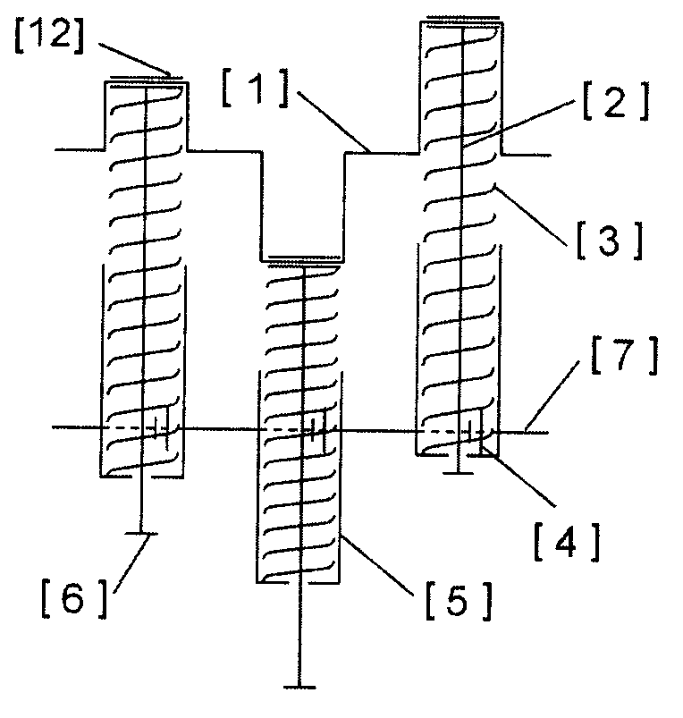
[0054] Example 1: Combining figure 1, the three (or appropriate number) connecting rods [2] of the crankshaft [1] are all installed (with a certain initial pressure or energy) compression springs (or compressible airtight air chambers) [3], and mutually form 120 degree angle (or equal angle), one end of the spring [3] is installed or tightly pressed on the shaft sleeve [12] of the connecting rod [2], and the other end is installed (or sleeved) on the bottom of the toothed spring seat [5] , the connecting rod [2] is movably connected with the toothed spring seat [5], and controls the movable range of the toothed spring seat [5] through the positioning (or braking) device [6] on the connecting rod [2], one-way The outer ring of the clutch (or locking mechanism) [4] processes the gear and meshes with the toothed spring seat [5], and the inner ring and the output shaft [7] are fixedly installed by splines or pin holes. In the process of torque transmission (or speed control), whe...
Embodiment 2
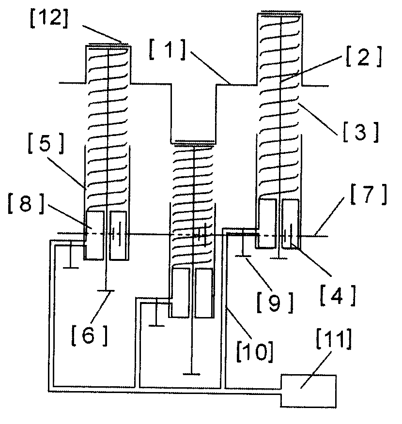
[0059] Example 2: Combining Figure 8 , Figure 9 , Figure 10 , it is three (or a suitable number) such as Figure 10 One end of shown elastic lever [86] is movably installed on crankshaft [1] through axle sleeve [90], and axle sleeve [90] space is advisable with longer so that crankshaft [1] can slide up and down in axle sleeve when rotating, The other end pin hole [91] is flexibly connected with the rack [83]; the support [87] is installed in the middle part of the elastic lever [86], and the support [87] can adopt Figure 9 Shown supporting structure, it is to install bearing [85] on the both sides of elastic lever [86] swing force, and bearing [85] warp shaft [89] is installed on the support [88], makes elastic lever [86] rotate It can move up and down during the torque transmission process; guide rails [84] are installed on both sides of the rack [83] so that the rack [83] can slide left and right on the guide rails [84], and the toothed outer ring of the one-way clut...
Embodiment 3
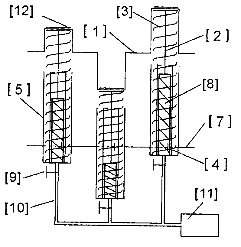
[0060] Example 3: Binding Figure 14 , it is that toothed connecting rod [2] is movably installed on the crankshaft [1] through the shaft sleeve [12], the transmission disc [35] is fixedly installed on the output shaft [7], the transmission disc [33] is installed movably, the transmission wheel [34], the transmission disc [33] is used as the outer ring (or inner ring) of the one-way clutch [4], and the transmission wheel [34] is used as the inner ring (or outer ring) of the one-way clutch [4] and is connected with the connecting rod The racks of [2] are meshed, and the two ends of the coil spring [13] are fixedly mounted on the transmission disc [35] and the transmission wheel disc [33] respectively, (the coil spring [13] can use one set or two sets and more than components). During the torque transmission process, the rotation of the crankshaft [1] causes the torque to be transmitted to the output shaft [7] by the toothed connecting rod [2] through the one-way clutch [4] to ...
PUM
 Abstract
Description
Claims
Application Information
 - R&D
- Intellectual Property
- Life Sciences
- Materials
- Tech Scout
- Unparalleled Data Quality
- Higher Quality Content
- 60% Fewer Hallucinations
Browse by: Latest US Patents, China's latest patents, Technical Efficacy Thesaurus, Application Domain, Technology Topic, Popular Technical Reports.
© 2025 PatSnap. All rights reserved.Legal|Privacy policy|Modern Slavery Act Transparency Statement|Sitemap|About US| Contact US: help@patsnap.com