Combustor fuel injection and mixing device

A fuel injection, fuel technology

Active Publication Date: 2013-04-24
AECC COMML AIRCRAFT ENGINE CO LTD
View PDF5 Cites 17 Cited by
  • Summary
  • Abstract
  • Description
  • Claims
  • Application Information

AI Technical Summary

Problems solved by technology

[0004] In the prior art, one of the design concepts of the low-pollution combustor is to adopt the method of staged fuel supply and zoned combustion. The problem of uneven oil supply in the circumferential direction will affect the outlet temperature distribution of the combustion chamber and adversely affect the life of the hot end parts of the aero-engine

Method used


Image

  • Combustor fuel injection and mixing device
  • Combustor fuel injection and mixing device

Examples


Embodiment Construction

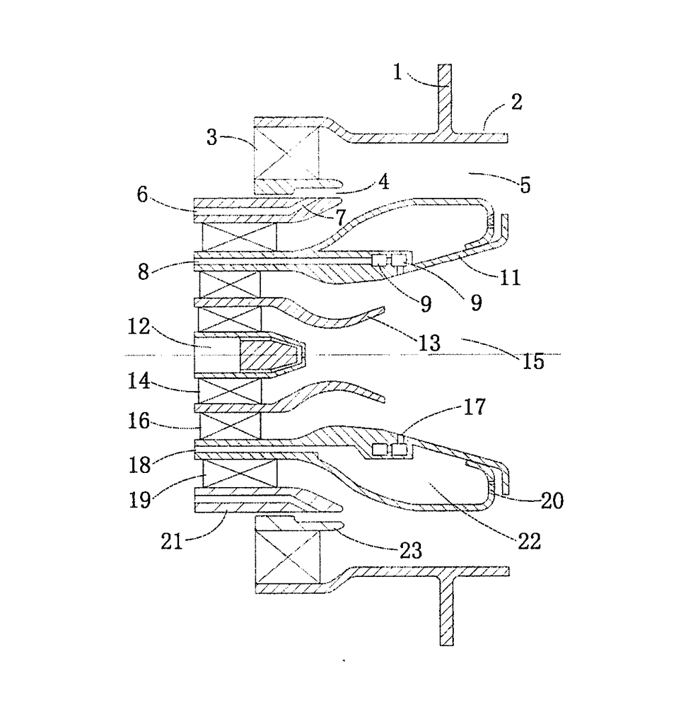
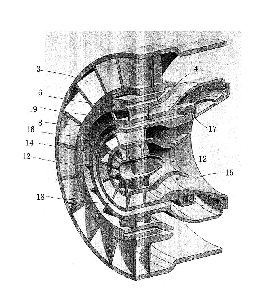
[0015] Such as figure 1 with 2 As shown, in the embodiment of the present invention, the combustion chamber fuel injection device is a fuel injection and oil-air mixing system composed of a fuel nozzle system and a swirler, which is connected to the head by installing the fitting surface 1 and the fitting surface 2 Segment and splash plate connections. The mating surface 2 is also the outer wall surface of the device.

[0016] Such as figure 2 As shown, the pre-combustion stage adopts a centrifugal nozzle 12 and a swirl cup 13 . A first-stage swirler 14 is arranged between the centrifugal nozzle and the swirl cup 13, and the first-stage swirler 14 is nested outside the centrifugal nozzle 12 and accommodated in the swirl cup 13 .

[0017] Both sides of the intermediate stage are provided with a second-stage cyclone 16 and a third-stage cyclone 19, wherein the second-stage cyclone 16 is between the swirl cup 13 and the inner wall of the intermediate stage, and the third T...


PUM


Abstract

Disclosed is a combustor fuel injection and mixing device. A main combustion level, a middle combustion level, and a pre-combustion level are sequentially arranged from outside to inside of the combustor fuel injection and mixing device. Fuel respectively flows into oil pipelines of the main combustion level, the middle combustion level and a pre-combustion level through a main combustion level oil inlet hole, a middle combustion level oil inlet hole and a pre-combustion level oil inlet hole. The fuel in the oil pipelines are injected into a main combustion level channel, a middle combustion level channel and a pre-combustion level channel through a main combustion level nozzle, a middle combustion level nozzle and a pre-combustion level nozzle. The main combustion level nozzle is a pre-film type nozzle. Wall surface of two sides of the main combustion level nozzle is an assembling surface for assembling. The main combustion level oil pipe after a curve section is gradually expanded into a slit to enable the fuel in the main combustion level oil pipeline to form a layer of oil film behind the outer side wall of the main combustion level nozzle. Swirler components capable of shearing and atomizing the fuel injected into the main combustion level channel under the act of swirling are arranged around the main combustion level nozzle. The combustor fuel injection and mixing device is capable of improving mixture evenness of fuel and gas in the main combustion level and further improving temperature distribution of the outlet of the combustor.

Description

technical field [0001] The invention relates to the field of power devices, in particular, to the improvement of fuel devices in combustion chambers of aero-engines. Background technique [0002] As atmospheric environmental issues receive more and more attention around the world, the low emission requirements of various power devices are also paid more and more attention. This is especially true for aero engines, where NOx emission requirements are reduced by 50% compared to existing engines in today's emission requirements. [0003] It has been proved by research that the emission of NOx increases gradually with the increase of local temperature, and with the increase of temperature, the increase rate of emission of NOx increases. It is known through experiments that when the temperature is higher than 1900K, the increase in temperature will lead to a sharp increase in NOx emissions. Therefore, controlling the gas temperature in the combustion chamber becomes the key to c...

Claims


Application Information

Patent Timeline
Patent Type & Authority Applications(China)
IPC IPC(8): F23R3/28
Inventor 曾庆林朱英李彬张漫何沛鄂亚佳郭德三吴昊李继保
Owner AECC COMML AIRCRAFT ENGINE CO LTD
Why Eureka
Try Eureka