Real-time monitoring system and method based on optical time domain reflection and fiber grating distributed type

An optical time domain reflection, distributed real-time technology, applied in measuring devices, measuring heat, using optical devices to transmit sensing components, etc., can solve the problems of inability to distinguish the change of the center wavelength of fiber gratings and the increase in the number of fiber gratings

Inactive Publication Date: 2013-04-24
WUHAN KPCQ SOFTWARE TECH
View PDF7 Cites 32 Cited by
  • Summary
  • Abstract
  • Description
  • Claims
  • Application Information

AI Technical Summary

Problems solved by technology

Many research institutions and companies at home and abroad have conducted a lot of research and development on it. At present, the main difficulty is how to accurately and quickly demodulate the center wavelength of each fiber Bragg grating, and monitor the shift of the center wavelength of each fiber Bragg grating in real time. In order to accurately reflect the measured changes of the outside world; secondly, because each fiber grating requires a cert...

Method used


Image

  • Real-time monitoring system and method based on optical time domain reflection and fiber grating distributed type
  • Real-time monitoring system and method based on optical time domain reflection and fiber grating distributed type

Examples


Embodiment Construction

[0026] The present invention will be further described below in conjunction with the accompanying drawings, embodiments, and the principle of optical time domain reflection:

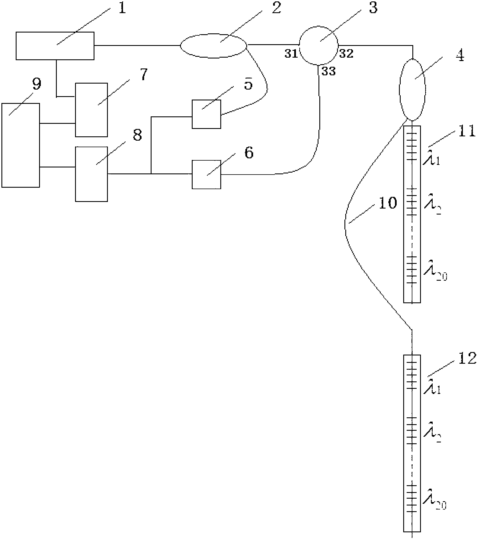
[0027] Such as figure 1 As shown, the distributed real-time monitoring system diagram based on optical time domain reflection and fiber Bragg grating technology. Here, two groups of fiber Bragg gratings are used as monitoring objects. If a longer distance needs to be monitored, it can be achieved by adding multiple groups of fiber Bragg gratings. The present invention includes a wavelength tunable laser 1, two fiber couplers (2, 4), an optical circulator 3, a laser wavelength monitoring unit 5, a photoelectric detector 6, a laser control unit 7, a signal processing unit 8, a computer 9, and a delay Optical fiber 10, the same two groups of fiber gratings (11, 12), wherein each group of fiber gratings includes twenty non-overlapping fiber grating sensing units; the laser control unit 7 is electrically conn...


PUM


Abstract

The invention relates to a real-time monitoring system and a method based on an optical time domain reflection and fiber grating distributed type. The real-time monitoring system is characterized in that a laser control unit is respectively connected with a laser device and a computer in an electric mode, the laser device is connected with a combined end of a first fiber coupler in an optical mode, two optical splitting ends of the first fiber coupler are respectively connected with a first optical circulator port and a laser device wavelength monitoring unit, a second optical circulator port is connected with a combined end of the second optical fiber coupler in an optical end, one shunting end of the second fiber coupler is connected with a group of fiber gratings in an optical mode, the other shunting ends are respectively connected with the other corresponding groups of fiber gratings in an optical mode through a delayed optical fiber, a third optical circulator port is connected with a photoelectric detector in an optical mode, and the laser device wavelength monitoring unit, the photoelectric detector and the computer are respectively connected with a signal collecting and processing unit in an electric mode. According to the real-time monitoring method, the central wavelength of the fiber gratings can be rapidly demodulated in a real-time mode, and changes of the central wavelength of the plurality of the fiber gratings which are coincided in a working waveband on a sensing periodic line can be distinguished.

Description

technical field [0001] The invention relates to the technical field of optical fiber sensing, in particular to a distributed real-time monitoring system and method using optical time domain reflection and optical fiber gratings. Background technique [0002] Distributed optical fiber sensing is a new type of real-time on-line monitoring technology that has gradually grown along with the needs of the society. The basic principle is to use an optical fiber to transmit and sense signals at the same time. Combined with advanced signal processing technology, it can detect up to dozens of Physical quantities such as temperature and strain at different positions of kilometers of optical fiber to achieve true distributed measurement. The unique advantages of optical fiber, such as light weight, anti-electromagnetic interference, and anti-corrosion, have also made distributed optical fiber sensors favored by many researchers and application units, and great progress has been made in ...

Claims


Application Information

Patent Timeline
IPC IPC(8): G01D5/36G01K11/32G01L1/24G01K11/3206
Inventor 张哲民杨帆张晓磊
Owner WUHAN KPCQ SOFTWARE TECH
Why Eureka
Try Eureka