Eureka AIR delivers breakthrough ideas for toughest innovation challenges, trusted by R&D personnel around the world.

Vibratory shock compound sensor for improving low frequency characteristic

A composite sensor and sensor technology, applied in vibration test, shock test, instrument, etc., to achieve the effect of guaranteeing the frequency range

Active Publication Date: 2013-04-24
北京唐智科技发展有限公司
View PDF7 Cites 13 Cited by
  • Summary
  • Abstract
  • Description
  • Claims
  • Application Information

AI Technical Summary

Problems solved by technology

[0020] The technical problem to be solved by the present invention is to provide a vibration-shock composite sensor with improved low-frequency characteristics in view of the deficiencies in the prior art, so as to solve the problem that the sensor base is not connected to the machine with high rigidity and the sensor inside is caused by the high rigidity of the connecting cable. respond to questions

Method used


Image

  • Vibratory shock compound sensor for improving low frequency characteristic
  • Vibratory shock compound sensor for improving low frequency characteristic
  • Vibratory shock compound sensor for improving low frequency characteristic

Examples


Embodiment 1

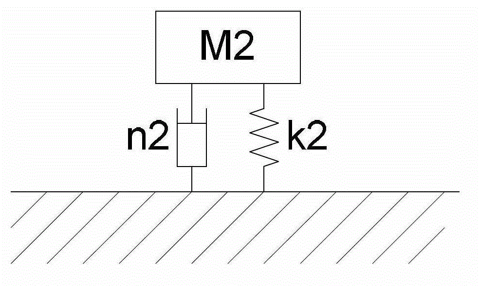
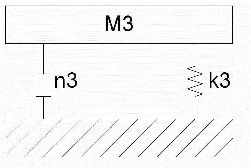
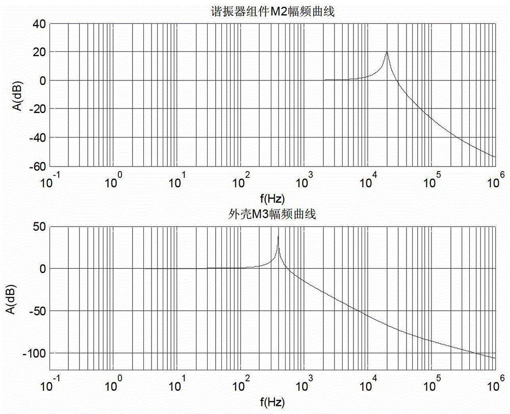
[0076] Assume that the mass of the sensor base of the sensor is M1=16g, the built-in spring mass generalized resonance resonance system of the sensor and the resonance mass of the resonator assembly M2=3g, the spring stiffness of the elastic element K2=4.75×10⁷N / m, and the set resonance damping n2=38Ns / m, the mass of the shell, cable clamp and cable installed on the sensor base is the mass of the upper cover M3=100g, the stiffness of the sensor shell K3=6×10⁵N / m, and the shell damping n3=3Ns / m. Let the machine mass M0=100kg, the original internal cable rigidity K41=7×10⁵N / m, and the internal cable rigidity improved by flexible PCB K42=14000N / m.

[0077] The desired sensor characteristics are: the resonant frequency f0=20±0.5kHz of the internal resonator components, the resonant gain G0=20±1dB, and the passband gain G1=0±1dB within 5.3kHz.

[0078] Before using the flexible PCB technology of the present invention, as attached Figure 13-1 The electromechanical equivalent simu...

Embodiment 2

[0081] On the basis of Example 1, the influence of the classic stud bolt connection and the connection with the tapered bolt of the present invention on the resonance system of the sensor is further tested.

[0082] The sensor base is coupled to a 100kg machine connection via classic nominal M5 studs. The connection stiffness of the classic stud bolts is set to 5×10⁸N / mN / m, which is about 10 times the stiffness of the resonator component of the sensor. The equivalent simulation is shown in the attached Figure 15-1 . The transfer characteristics of the sensor are as attached Figure 15-2 And attached Figure 15-3 : The resonant frequency f0=20.18kHz of the resonator assembly is qualified; but the resonant gain G0=8.483dB is unqualified; the gain exceeds 1dB at 2.8kHz, and there is also elasticity formed by the sensor base mass M1 and the nominal value M5 bolts The resonance peak of 9268Hz and 39.49dB produced by the quality system is unqualified.

[0083] The sensor base o...


PUM

PropertyMeasurementUnit
Spring rateaaaaaaaaaa
Stiffnessaaaaaaaaaa
Stiffnessaaaaaaaaaa

Abstract

The invention discloses a vibratory shock compound sensor for improving a low frequency characteristic. Through high-rigidity connection coupling of a sensor base and a machine and through low-rigidity connection of a resonator assembly inside a sensor and cables by a flexible printed circuit board (PCB), wide frequency ranges of low-frequency vibration detection of the sensor are effectively guaranteed, and high-frequency generalized resonance stability of the resonator assembly needed in shock resonance demodulation detection is ensured. Thus, an engineering vibratory shock compound sensor which is high in reliability and practicability and a machine structure design implementation approach of the engineering vibratory shock compound sensor are supplied to rail transit, wind power generation and other mechanical fault diagnosis.

Description

technical field [0001] The invention relates to the field of vibration and shock resonance demodulation and detection for engineering applications, in particular to a vibration and shock composite sensor with improved low-frequency characteristics. Background technique [0002] The inventor has previously proposed a number of sensor technology patents related to vibration shock detection, such as: [0003] 200710036156.5 A magnetically mounted vibration shock sensor [0004] 200710036153.1 A broadband charge amplifier and its design method [0005] 01233313.1 Temperature vibration digital-analog composite sensor [0006] 200720062217.0 A Composite Sensor for Simultaneously Detecting Horizontal Vibration and Vertical Vibration and Shock [0007] 200810200735.3 A Generalized Resonance Composite Sensor for Detecting Vibration and Shock [0008] 200720065122.4 Magnetically mounted vibration shock sensor [0009] The composite sensor for vibration and shock detection compose...

Claims


Application Information

Patent Timeline
IPC IPC(8): G01M7/02G01M7/08G01D11/26G01D11/30
Inventor 唐德尧张弸
Owner 北京唐智科技发展有限公司
Why Eureka
Eureka Blog
Learn More