Adjustable multifunctional circulation test groove platform

A flow test and test tank technology, which is applied in the geotechnical field of civil engineering, can solve the problems of single function of the device and the inability of the test device to provide a platform, and achieve the effect of multiple functions, strong repeatability and easy operation

Active Publication Date: 2013-04-24
NORTHEASTERN UNIV
View PDF1 Cites 20 Cited by
  • Summary
  • Abstract
  • Description
  • Claims
  • Application Information

AI Technical Summary

Problems solved by technology

[0007] Existing test devices are often designed for a specific situation, and the test needs to consider problems from multiple perspectives, so the existing test devices cannot provide a suitable platform;
[0008] 2. The function of the device is single:
[0009] Because when doing simulation tests, it is often necessary to verify the influence of several or even multiple parameters on the test results, the existing test devices have great disadvantages for the test

Method used


Image

  • Adjustable multifunctional circulation test groove platform
  • Adjustable multifunctional circulation test groove platform
  • Adjustable multifunctional circulation test groove platform

Examples


Embodiment 1

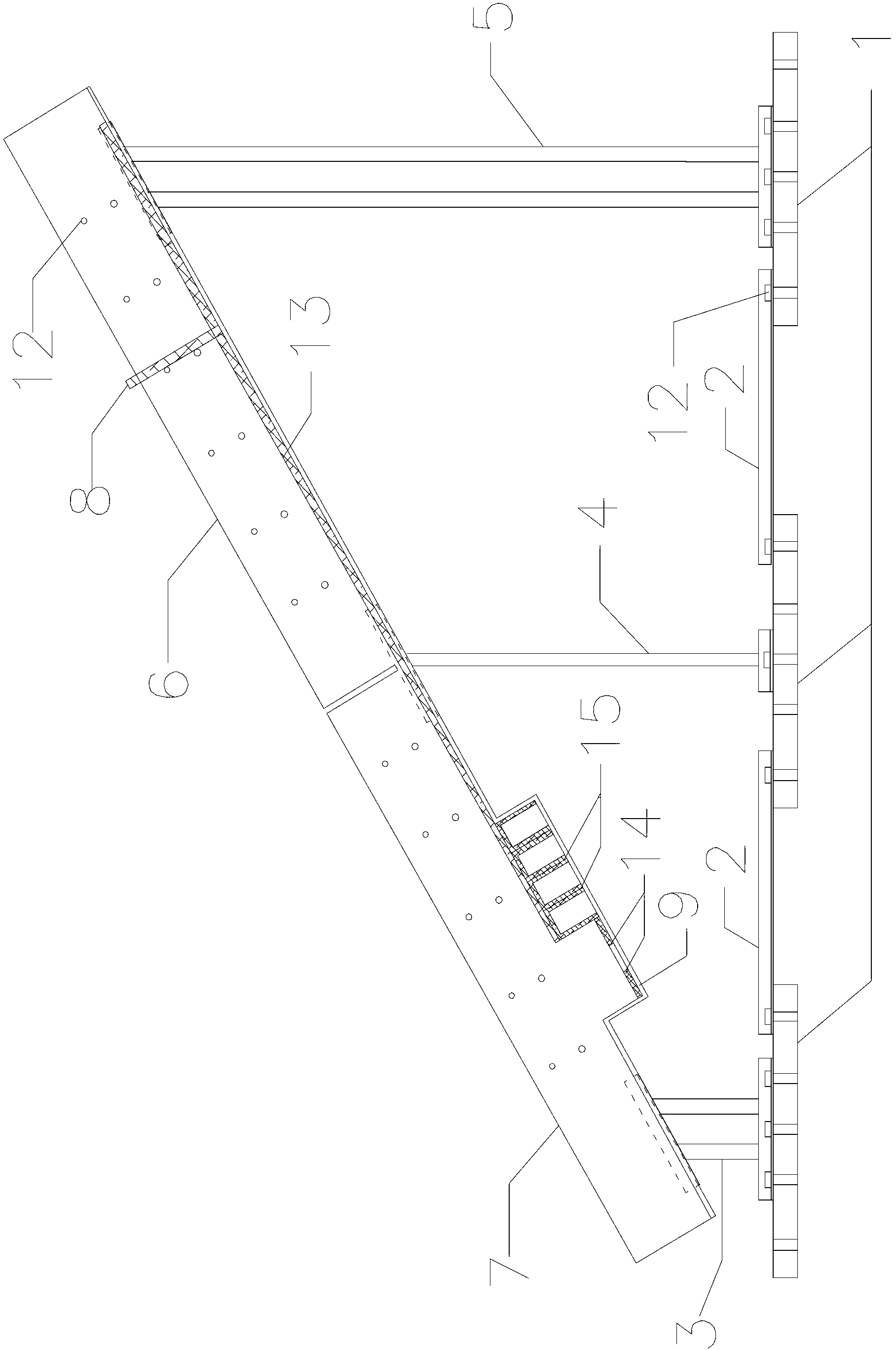
[0036] Such as figure 1 As shown, firstly, the base support plate 1 is placed on the flat ground according to the required distance, and the corresponding erosion belt support 3, transition support 4 and sliding track support 5 are selected according to the angle required by the test, and the erosion belt support 3, transition support 4 and The inclination angles of the sliding track brackets 5 are the same; then the three are placed on the corresponding base support plate 1 in turn, and the four are assembled together by the threaded fasteners 12; finally, the base connecting rods are connected by the threaded fasteners 12 2 and the base support plate 1 are connected together to form a bracket assembly.

Embodiment 2

[0038] Such as figure 2 As shown, firstly, the base support plate 1 is placed on the flat ground according to the required distance, and the corresponding erosion belt support 3, transition support 4 and sliding track support 5 are selected according to the angle required by the test, and the erosion belt support 3, transition support 4 and The inclination angles of the sliding track brackets 5 are different; then the three are placed on the corresponding base support plate 1 in turn, and the four are assembled together by the threaded fasteners 12; finally, the base connecting rods are connected by the threaded fasteners 12 2 and the base support plate 1 are connected together to form a bracket assembly.

[0039] (2) Installation of slide track test tank 6 and erosion zone test tank 7:

[0040] Such as figure 1 , 2 As shown, respectively place the sliding track test tank 6 and the erosion zone test tank 7 on the previously assembled support assembly as required, and adjus...


PUM


Abstract

The invention discloses an adjustable multifunctional circulation test groove platform, belongs to the technical field of ground in civil engineering, and particularly relates to an adjustable multifunctional circulation test groove platform which imitates a debris flow motor process erosion effect along a way. The adjustable multifunctional circulation test groove platform is detachable, capable of being combined, convenient to operate and strong in repeatability, and comprises an erosion band support, a transition support, a sliding-down rail support, a sliding-down rail test groove and an erosion band test groove. The upper end of the sliding-down rail groove is installed on the sliding-down rail support, the lower end of the sliding-down rail groove is installed on the transition support, the upper end of the erosion band test groove is installed on the transition support, the lower end of the erosion band test groove is installed on the erosion band support, an erosion material sliding-down control partition plate is arranged in the sliding-down rail test groove, an initial material sliding-down area is arranged at the back of the erosion material sliding-down control partition plate, a corroded material placing groove is formed in the erosion band test groove, and the erosion band support, the transition support and the sliding-down rail support are respectively installed on a base support plate.

Description

technical field [0001] The invention belongs to the technical field of geotechnical engineering in civil engineering, and in particular relates to an adjustable multifunctional circulation test tank platform for simulating erosion along the process of mud-rock flow movement. Background technique [0002] In recent years, under the influence of factors such as human activities and climate change, the frequency of debris flow disasters has become more frequent and the scale of outbreaks has become larger and larger. The outbreak of mudslides often destroys roads and bridges, obliterates land and houses, blocks rivers and waterways, affects people's normal life, and even threatens people's lives and property safety. It has become an important factor restricting the economic development of mountainous areas. People have carried out investigation and research on debris flow in many fields such as water conservancy and hydropower projects, industrial and civil buildings, road and ...

Claims


Application Information

Patent Timeline
Patent Type & Authority Applications(China)
IPC IPC(8): G01M10/00
Inventor 王述红昝世明王存根樊赟赟倪勇黄立夫王一然高轩麟
Owner NORTHEASTERN UNIV
Why Eureka
Try Eureka