Switching room user identification method and switching room user identification device

A user identification and user technology, applied to instruments, digital measurement technology for measurement, measuring devices, etc., can solve the problems of high power, short circuit, long distance, etc., and achieve high reliability

Inactive Publication Date: 2013-04-24
余力鑫
View PDF6 Cites 21 Cited by
  • Summary
  • Abstract
  • Description
  • Claims
  • Application Information

AI Technical Summary

Problems solved by technology

The method of using power carrier communication to identify users has two obvious disadvantages: First, in the case of adjacent substations sharing high voltage, common ground, parallel wiring, and common cable trench, it is easy to cause misjudgment due to the cross-connection of carrier signals ; Second, the power carrier signal is a high-frequency signal with severe attenuation. Users with long distances and large line interference cannot be identified, and the accuracy of user identification cannot be guaranteed to reach 100%.
[0005] The above measurement methods require the measuring instrument to be in direct contact with the power line, require a large power, and require an external power supply, which cannot be achieved in some sites.
In addition, the connection between the measuring instrument and the power line is likely to cause a short circuit. In addition, some of the household lines are hidden lines, and only the electric meter has a very short connection line. The above-mentioned instruments have no way to measure at all. ACCIDENT

Method used


Image

  • Switching room user identification method and switching room user identification device
  • Switching room user identification method and switching room user identification device
  • Switching room user identification method and switching room user identification device

Examples


Embodiment Construction

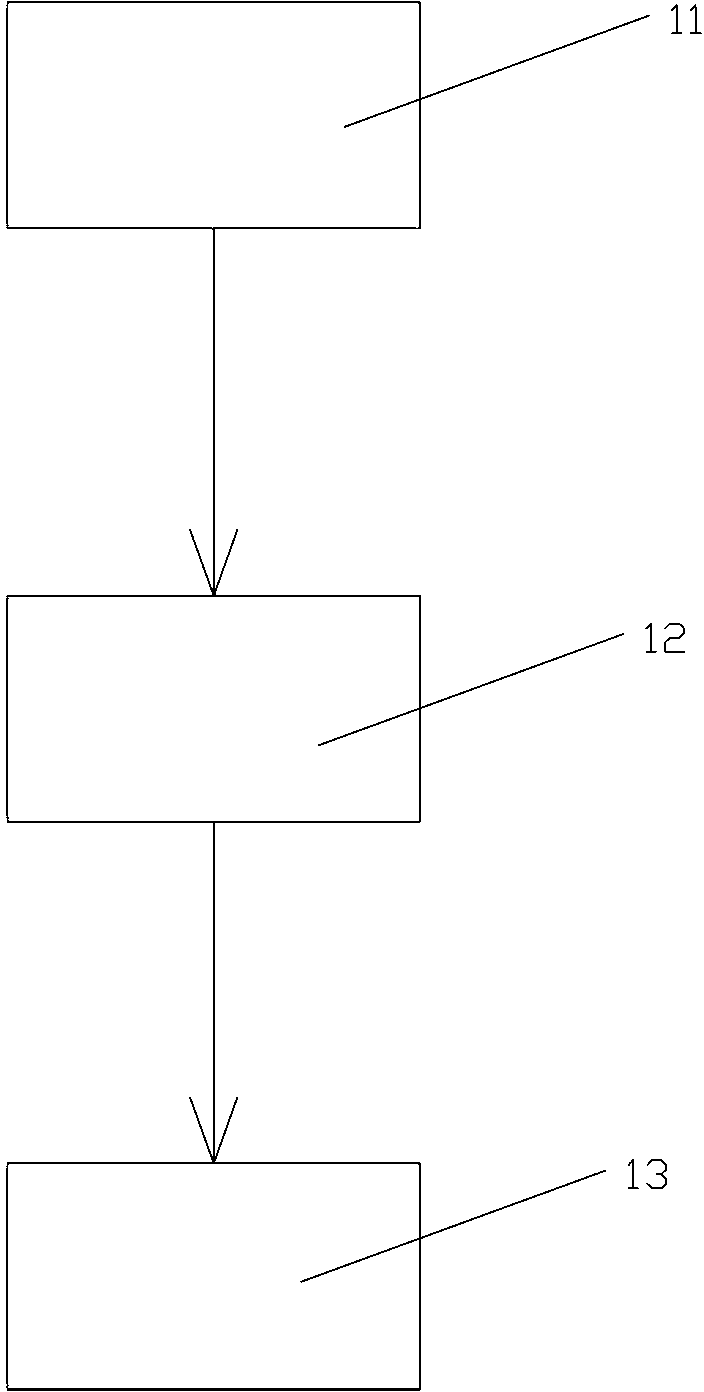
[0044] See figure 1 , figure 1 Disclosed is a method for user identification in a station area, comprising:

[0045]11) Clamp the user identification device on the line of the identified user through its current clamp, and the user identification device starts to detect the power supply status data of the line of the identified user; when the power supply state of the line of the identified user changes from one state to In another state, the user identification device must at least judge and record the time data when the power supply state changes;

[0046] 12) Artificially cut off or restore power to the line of the identified user at least once, and manually record the time of power failure or power restoration;

[0047] 13) Compare the time data recorded by the user identification device when the power supply state changes with the manually recorded power-off time or power-recovery time, if the two match, the identified user belongs to the set station area, otherwise, it...


PUM


Abstract

Disclosed are a switching room user identification method and a switching room user identification device. The identification method comprises that the user identification device is clamped on a circuit of an identified user, and when a power-supplying state of the identified user changes from one state to another state, the user identification device adjusts and notes data of the moment the power-supplying state changes; outage or delivery of currents is conducted on the circuit of the identified user so as to note moment of the outage and moment of the delivery of the currents; data noted by the user identification device at the moment the power-supplying state changes is compared with the manually noted moment of the outage or manually noted moment of the delivery of the currents, and if the data noted by the user identification device at the moment the power-supplying state changes fits the manually noted moment of the outage or manually noted moment of the delivery of the currents, the identified user belongs to a preset switching room, or the identified user does not belong to the preset switching room. The identification device only needs clamping on a coat of the circuit of the user, and a current with a capacity of only 0.005A is needed on the circuit, namely, self-consumption of a watt hour meter can generate a current with a capacity of more than 0.005A as long as the user is provided with the watt hour meter and the watt hour meter normally works. Therefore, self-consumption of the watt hour meter can be detected by the identification device, and high detection reliability is guaranteed.

Description

technical field [0001] The invention relates to a station area user identification method and a station area user identification device for electric power management. Background technique [0002] In the general survey of power consumption management of power supply enterprises, it was found that there was a discrepancy between the customer's station area and the marketing system information at the intersection of the station area, but it could not be identified because of the large number of power lines or buried underground. Or due to historical reasons, the routing of user lines in urban villages has always been chaotic. Some users even have two access lines, which belong to different station areas. It is required to carry out wiring. This phenomenon causes a large error between the sum of user power in the station area and the data of the gateway meter. More because of chaotic connection, the existence of chaotic build phenomenon also causes great personal safety hidden...

Claims


Application Information

Patent Timeline
Patent Type & Authority Applications(China)
IPC IPC(8): G01R31/00G01R19/25
Inventor 余力鑫
Owner 余力鑫
Why Eureka
Try Eureka