Photoelectric switch

A photoelectric switch and light-receiving part technology, applied in electronic switches, electrical components, optical device exploration, etc., can solve the problem that the light-receiver cannot distinguish which light-emitting device the light signal comes from, and achieve the effect of preventing and reducing misjudgments

Inactive Publication Date: 2013-04-24
YAMATAKE HONEYWELL CO LTD
View PDF9 Cites 11 Cited by
  • Summary
  • Abstract
  • Description
  • Claims
  • Application Information

AI Technical Summary

Problems solved by technology

However, information other than optical signals is not exchanged between the paired emitter and receiver, so the receiver cannot distinguish from which emitter the received optical signal comes from

Method used


Image

  • Photoelectric switch
  • Photoelectric switch
  • Photoelectric switch

Examples


Embodiment approach 1

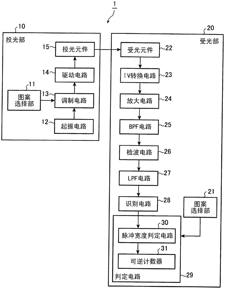
[0048] figure 1 The shown photoelectric switch 1 is a transmissive photoelectric switch including a light projecting part 10 and a light receiving part 20 sandwiched between detection areas in a face-to-face state. Whether there is a detection target object in the area.

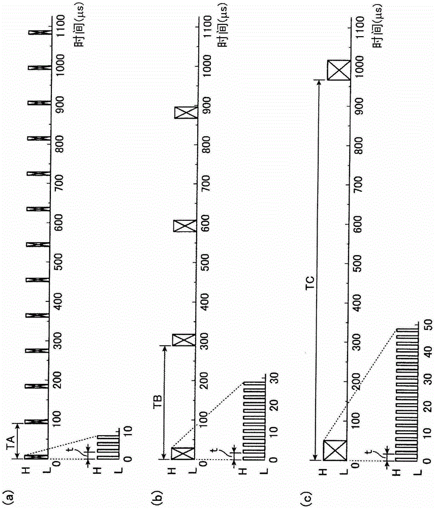
[0049] In Embodiment 1, a configuration will be described assuming that a maximum of three photoelectric switches 1 are connected and used. The three photoelectric switches 1 (referred to here as photoelectric switches 1A~1C) are composed of three light projecting parts 10 with different light emitting pulse periods and pulse widths, and based on the received light period and pulse width, the pair is automatically Three light receiving units 20 for discriminating whether to emit light or to interfere with light are constituted.

[0050] Here, self-luminescence refers to light received by the light receiving unit 20 of the photoelectric switch 1A from the light projecting unit 10 of the same photoelectric s...


PUM


Abstract

A transmitter (10) projects light in accordance with a specific light projecting pattern, selected by a pattern selecting portion (11), of three light projecting patterns A through C having mutually differing projected light periods and projected light pulse widths. A pulse width evaluating circuit (30) of a detector (20) detects, as a difference in pulse width of a detected light signal, the difference in the projected light pulse width of the light projecting pattern, based on the same light projecting pattern pulse width information as the transmitter (10), selected by a pattern selecting portion (21), to identify locally-emitted light versus interference light.

Description

technical field [0001] The invention relates to a photoelectric switch which detects a detection object according to the change of the received light amount. Background technique [0002] A transmissive photoelectric switch includes a set of light emitters and light receivers, and detects changes in the amount of light based on the presence or absence of shading by a detection object passing through the light path (see, for example, Patent Document 1). Figure 5 This is an illustration of the case where the transmissive photoelectric switch is used in a three-unit state. Light projectors 100A to 100C are arranged on one side of a detection area through which a detection object passes, and light receivers 200A to 200C are arranged on the other side. In this example, the light projector 100A and the light receiver 200A are a pair, the light projector 100B and the light receiver 200B are a pair, and the light projector 100C and the light receiver 200C are a pair. For example, t...

Claims


Application Information

Patent Timeline
Patent Type & Authority Applications(China)
IPC IPC(8): H03K17/94
CPCG01V8/20H03K17/943
Inventor 畑中浩中尾隆志佐佐木宏铃木慎一郎
Owner YAMATAKE HONEYWELL CO LTD
Why Eureka
Try Eureka