A diaphragm with low frequency compensation function and its preparation method

A functional and low-frequency technology, which is applied in the field of diaphragm with low-frequency compensation and its preparation, can solve the problems of high resonance frequency, high mechanical strength, and cold sound, and improve and increase the phenomenon of cold sound. The effect of low frequency output

Active Publication Date: 2015-11-25
SUZHOU YICHUAN TECH CO LTD
View PDF5 Cites 0 Cited by
  • Summary
  • Abstract
  • Description
  • Claims
  • Application Information

AI Technical Summary

Problems solved by technology

[0002] The generator unit includes a moving iron unit, a shielding shell, and a sounding tube. The moving iron unit is the main part of the sound. The moving iron unit includes a diaphragm and a magnetic drive mechanism. The magnetic drive mechanism of the traditional moving iron unit has a high electromagnetic conversion efficiency. The iron sheet in the driving mechanism has a higher resonance frequency due to its greater mechanical strength, so the amplification of the sound signal in the middle and high frequency bands is stronger than the amplification of the low frequency sound signal, resulting in a colder sound from the moving iron unit , there is an urgent need for a moving iron unit that can solve the problem

Method used


Image

  • A diaphragm with low frequency compensation function and its preparation method
  • A diaphragm with low frequency compensation function and its preparation method
  • A diaphragm with low frequency compensation function and its preparation method

Examples


Embodiment 1

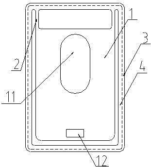
[0026] see figure 1 , as shown in the legend therein, a diaphragm with low-frequency compensation function, including a diaphragm main body 1, two connecting parts 2, a diaphragm support 3 and a prestressed film 4, the prestressed film 4 is fixed tight and Sealed on the diaphragm support 3; one end of the diaphragm main body 1 is connected to the diaphragm support 3 through the connecting part 2, the diaphragm main body 1 includes a front and a back; the front is in contact with the prestressed film 4; the diaphragm A cavity 11 and a connecting hole 12 are also defined on the main body 1 .

[0027] The cavity 11 communicates with the above-mentioned front and back surfaces, and the cross section of the cavity 11 is elliptical.

[0028] The cross-sectional areas of the cavities on the front and back are 25% of the areas of the front and back respectively.

[0029] The diaphragm main body 1 , the connection part 2 and the diaphragm holder 3 are made of aluminum.

[0030] The ...

Embodiment 2

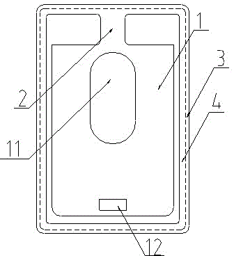
[0034] The rest is the same as the first embodiment, except that the diaphragm includes a diaphragm main body 1 , a connecting portion 2 , a diaphragm support 3 and a prestressed film 4 .

Embodiment 3

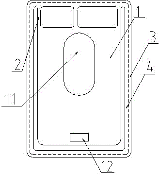
[0036] The rest is the same as the first embodiment, except that the diaphragm includes a diaphragm main body 1 , three connecting parts 2 , a diaphragm support 3 and a prestressed film 4 .


PUM


Abstract

The invention discloses a vibration diaphragm with a low frequency compensation function. The vibration diaphragm with the low frequency compensation function comprises a vibration diaphragm main body, a connecting part, a vibration diaphragm support and a prestress diaphragm, wherein the vibration diaphragm main body comprises an obverse and a reverse, the obverse or the reverse is attached to and contacted with the prestress diaphragm, a cavity body is further formed in the vibration diaphragm main body, the prestress diaphragm is fixedly tightened and arranged on the vibration diaphragm support in a sealing mode, and one end of the vibration diaphragm is connected on the vibration diaphragm support through the connecting part. The cavity body is formed in the vibration diaphragm, low frequency output is increased through the fact that mechanical strength of the vibration diaphragm is reduced partially, low frequency compensation can be generated through high frequency resonance of the low frequency output and an iron sheet, and therefore a phenomenon of cold listening feel of an original iron moving unit is improved. Further disclosed is a preparation method of the vibration diaphragm.

Description

technical field [0001] The invention relates to a vibrating membrane, in particular to a vibrating membrane with low frequency compensation function and a preparation method thereof. Background technique [0002] The generator unit includes a moving iron unit, a shielding shell, and a sounding tube. The moving iron unit is the main part of the sound. The moving iron unit includes a diaphragm and a magnetic drive mechanism. The magnetic drive mechanism of the traditional moving iron unit has a high electromagnetic conversion efficiency. The iron sheet in the driving mechanism has a higher resonance frequency due to its greater mechanical strength, so the amplification of the sound signal in the middle and high frequency bands is stronger than the amplification of the low frequency sound signal, resulting in a colder sound from the moving iron unit , there is an urgent need for a moving iron unit that can solve the problem. Contents of the invention [0003] In order to sol...

Claims


Application Information

Patent Timeline
Patent Type & Authority Patents(China)
IPC IPC(8): H04R7/02H04R7/16H04R31/00
Inventor 李梁周巍
Owner SUZHOU YICHUAN TECH CO LTD
Why Eureka
Try Eureka