Stereotaxic Radiation Therapy Unit

A radiotherapy and stereotaxic technology, applied in radiotherapy, treatment, and radiodiagnostic instruments, can solve the problems of unstable radiation, heavy accelerator, manufacturing difficulty and cost increase, and achieve cost-effective control and dose distribution. Uniform, precise results

Active Publication Date: 2015-12-30
SUZHOU LINATECH MEDICAL SCI & TECH CO LTD
View PDF4 Cites 3 Cited by
  • Summary
  • Abstract
  • Description
  • Claims
  • Application Information

AI Technical Summary

Problems solved by technology

The accelerator of the current radiotherapy equipment can only rotate around the Z axis, and the rays emitted by the accelerator can only be limited to the plane perpendicular to the Z axis, and the incident angle cannot be freely selected, which brings great constraints to the examination of diseases and directional irradiation treatment
[0003] In view of the above problems, the prior art has proposed a solution, that is, the accelerator is suspended on a slide rail parallel to the Z axis, which can slide back and forth, and the accelerator head can be Swing on the YZ plane, the accelerator rotates with the accelerator bracket in the XY plane, and cooperates with the swing on the YZ plane to realize three-dimensional and multi-angle irradiation. However, because the accelerator is heavy, its suspension and driving structure are very complicated and the cost is high. In addition, the ray is unstable due to the swing of the accelerator, and the transmission system of the accelerator is closely connected with the accelerator, which may also interfere with the treatment system, which increases the difficulty and cost of manufacturing. In addition, the accelerator cannot maintain a corresponding working state with the digital image detection panel during the swing process, so Unable to detect the treatment effect at any time, and carry out further correction and treatment

Method used


Image

  • Stereotaxic Radiation Therapy Unit
  • Stereotaxic Radiation Therapy Unit
  • Stereotaxic Radiation Therapy Unit

Examples


Embodiment 1

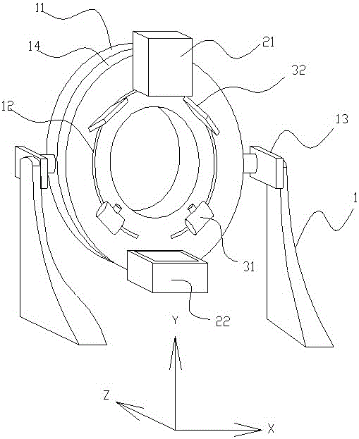
[0056] Such as figure 1 As shown, a stereotactic radiation therapy device includes an MV-level accelerator 21, and also includes: an accelerator bracket, an X-axis rotating device 13 and a frame 1 for driving the accelerator bracket to rotate around the X-axis; and a Z-axis rotating bracket 14 (also can be integrated on the accelerator), the MV-level accelerator 21 is installed on the adapter. The adapter is not shown in the figure, and it is fixedly installed (or detachable, movable, or transmission installed) on the Z-axis rotating bracket 14, and it can also be integrally formed with the MV-level accelerator 21, or assembled as a whole.

[0057] The accelerator bracket includes an X-axis rotation bracket 11 and a Z-axis rotation bracket 14, and the Z-axis rotation bracket 14 is set on the X-axis rotation bracket 11 and can rotate back and forth around its central axis, that is, the Z axis; the 4D The stereotaxic radiation therapy device also includes an MV-level digital im...

Embodiment 2

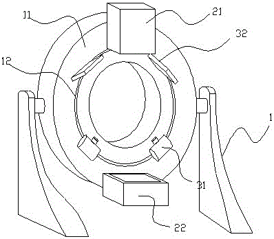
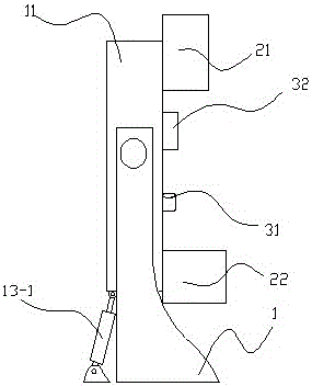
[0083] Such as figure 2 , image 3 As shown, the rest are the same as in Embodiment 1, the difference is that the X-axis rotating device is a hydraulic device, and one end of the hydraulic device is hinged on the base of the frame 1 (when the frame only has two directly fixed When it is a pillar on the ground, the hydraulic device is directly installed on the ground), and the other end is hinged on the accelerator bracket. The action of raising the head and nodding of the accelerator bracket and the accelerator 22 is promoted by the piston rod of the hydraulic device, and the accelerator bracket (in essence, the X-axis rotating bracket 11) and the frame 1 are movably connected through a rotating shaft and a bearing, and also It can be flexibly connected in the form of shaft and shaft sleeve. Above-mentioned hydraulic device also can be replaced by screw rod pushing device or pneumatic device.

Embodiment 3

[0085] Such as figure 2 , Figure 4 As shown, the rest are the same as in Embodiment 1, except that the X-axis rotating device includes an arc-shaped rack fixed on the base of the frame (when the frame only has two pillars directly fixed on the ground) , directly on the ground), the gear that is arranged on the accelerator bracket and meshes with the arc rack. By controlling the rotation of the gear (which can be driven by the servo motor) arranged on the accelerator bracket, the gear moves up and down along the arc-shaped entry, driving the accelerator bracket and the accelerator to complete the actions of raising the head and nodding.

[0086] The beneficial effects of adopting this technical solution are: the accelerator bracket, the X-axis rotating device and the frame that drive the accelerator bracket to rotate around the Z-axis and the X-axis respectively, and the adapter arranged on the accelerator bracket, and the accelerator is installed on the On the adapter, the...


PUM


Abstract

A stereo positioning radiation therapy device comprises: an accelerator (21), an accelerator bracket, an X-axis rotation device (13) for driving the accelerator bracket to rotate about an X-axis and a frame (1), and an adapter disposed on the accelerator bracket. The accelerator (21) is installed above the adapter, and the accelerator bracket and the frame (1) are in a transmission connection through the X-axis rotation device (13), so that the accelerator (21) can perform nodding and looking-upward actions following the accelerator bracket, thereby changing the irradiation angle of a ray emitted by the accelerator (21) with respect to a Z-axis. As a result, the irradiation angle can be adjusted in the three-dimensional space, instead of merely being changed in the two-dimensional plane originally, thereby significantly improving the degree of freedom of adjustment, which provides greater supports for accurate detection and treatment.

Description

technical field [0001] The invention relates to a medical device, in particular to a 4D stereotaxic radiotherapy device used in conjunction with an accelerator therapy instrument. Background technique [0002] When radiotherapy is performed on a tumor (target area), precise positioning of the tumor is required. In the 3D space, the doctor or physicist first scans the patient's CT images in the CT room, and reconstructs a series of CT images into a 3D image through an algorithm. At this time, the 3D coordinates of the tumor in the 3D image can be located. Then the doctor or physicist places the patient in the accelerator room for reset, and precisely coincides the three-dimensional coordinates of the tumor with the treatment isocenter of the accelerator. Finally start treatment. The accelerator of the current radiotherapy equipment can only rotate around the Z axis, and the rays emitted by the accelerator can only be limited to the plane perpendicular to the Z axis, and the...

Claims


Application Information

Patent Timeline
Patent Type & Authority Patents(China)
IPC IPC(8): A61B6/03A61N5/00
CPCA61N5/1081A61B6/4447
Inventor 姚毅
Owner SUZHOU LINATECH MEDICAL SCI & TECH CO LTD
Why Eureka
Try Eureka