Narrow-gap welding nose with tilt angle device

A welding head and narrow gap technology, which is applied to welding equipment, electrode support devices, manufacturing tools, etc., can solve the problems of reducing meaning, large welding torch size, and increasing groove gap, so as to reduce manufacturing costs and improve economic benefits , small size effect

Active Publication Date: 2013-05-01
北京嘉克新兴科技有限公司
View PDF7 Cites 14 Cited by
  • Summary
  • Abstract
  • Description
  • Claims
  • Application Information

AI Technical Summary

Problems solved by technology

The disadvantage is that it requires a special twin-wire welding torch, two sets of power supplies, two sets of wire feeding systems

Method used


Image

  • Narrow-gap welding nose with tilt angle device
  • Narrow-gap welding nose with tilt angle device
  • Narrow-gap welding nose with tilt angle device

Examples


Embodiment 1

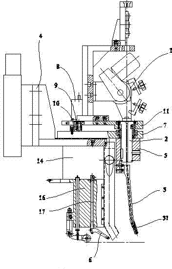
[0033] in figure 1 In the first embodiment shown, the corner sleeve 5 is fixed to the guide screw 2; the swing angle mechanism is also provided with a fixed plate 7, a swing angle motor 8, and a driving gear 9 arranged on the swing angle motor shaft. , The swing angle gear ring 10 and the swing plate 11 meshing with the driving gear; the fixed plate 7 is insulated and fixed with the connecting plate 4; the guide screw 2 is pivotally arranged with the fixed plate 7, and the swing angle tooth The ring 10 is fixed to the fixed plate 7, the guide wire rod 2, the swing angle motor 8 and the wire feeding device 1 are all fixed on the swing plate 11, and the rotation axis of the swing angle gear ring and the The swing axis of the swing plate is coaxial with the guide screw.

[0034] When one side of the weld groove needs to be welded, the controller controls the swing angle motor 8 to rotate. Because the swing angle gear ring 10 is fixed on the fixed plate, the swing angle motor shaft m...

Embodiment 2

[0036] The corner sleeve 5 is fixed to the guide screw 2; the swing angle mechanism is also provided with a fixed plate 7, a swing angle motor 8, a driving gear 9 arranged on the swing angle motor shaft, and a pendulum meshing with the driving gear Angle gear 10 and swing plate 11; said fixed plate 7 and said connecting plate 4 are insulated and fixed; said guide screw 2 and said fixed plate 7 are pivoted, said swing angle motor 8 and said fixed plate 7 Fixed, the swing angle gear ring 10, the wire feeding device 1, the guide screw 2 and the swing plate 11 are fixed; and the rotation axis of the swing angle ring gear and the swing axis of the swing plate are connected to the guide wire The rod is coaxial.

[0037] When it is necessary to weld one side of the weld groove, the controller controls the swing angle motor 8 to rotate, and the swing angle gear is driven to rotate by an angle around the rotation axis through the driving gear. Because the swing angle gear 10 is fixed on t...

Embodiment 3

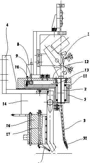
[0039] Such as figure 2 As shown, the corner sleeve 5 is pivoted to the guide screw 2 through a bearing; the swing angle mechanism is also provided with a fixed plate 12, a swing angle motor 8, and a driving gear 9 arranged on the shaft of the swing angle motor 8. , The swing angle gear ring 10 and the swing plate 11 meshing with the driving gear 9; the fixed plate 12 is insulated and fixed with the connecting plate 4, and a fan-shaped hole 13 is provided in the middle; the wire feeding device 1 and the guide wire The rod 2 is fixed on the fixed plate 12, the swing plate 11 is set in the fan-shaped hole 13 of the fixed plate 12, and the corner sleeve 5 is located at the tip of the fan-shaped hole, the swing angle gear ring 10 is fixed to the swing plate 11 and parallel to the arc of the fan-shaped hole, and the swing angle motor 8 is fixed to the fixed plate 12.

[0040] The difference between this embodiment and the first and second embodiments is that the swing part of the wel...


PUM


Abstract

The invention relates to a narrow-gap welding nose with a tilt angle device, which carries out narrow-gap welding. The narrow-gap welding nose with the tilt angle device comprises an electric conduction nozzle of a welding gun, a connecting plate for installing the welding gun, and a tilt angle device, wherein the lower end of the electric conduction nozzle is provided with a bent part; and the bent part is coaxially and fixedly arranged on the lower end of a wire guide rod by a corner sleeve. The narrow-gap welding nose with the tilt angle device is characterized in that the tilt angle device comprises a tilt angle mechanism for driving the electric conduction nozzle to carry out deflection, and a side wall tracking mechanism for keeping the distance between the electric conduction nozzle and the side wall, wherein the tilt angle mechanism for driving the electric conduction nozzle to carry out deflection is connected with the electric conduction nozzle; the side wall tracking mechanism comprises an oscillating rod, an angle sensor and a controller, wherein the oscillating rod is used for supporting the side wall of a groove; the angle sensor is connected with the oscillating rod and is connected with the controller; the controller controls the tilt angle mechanism; and the oscillating rod and the side wall of the groove are always in elastic contact. The lateral displacement moving amount of a workpiece is measured by a high-precision sensing assembly, and the distance between the electric conduction nozzle and the workpiece is controlled to be within a tracking precision of +/-0.5mm by the lateral regulation of the control system so as to guarantee the stable and even penetration of the side wall.

Description

Technical field [0001] The invention relates to a narrow gap welding head in the field of welding equipment, in particular to a narrow gap welding head with a swing angle device for single-wire double-pass multilayer narrow-gap welding. Background technique [0002] Narrow gap welding is used for butt welding of thick plates. No groove or only a small angle bevel before welding, and a narrow and deep gap is left. The entire weld is completed by multi-layer welding of gas shielded welding or submerged arc welding . Due to the small groove gap, the cross-sectional area of ​​the thick plate weld is greatly reduced, thereby reducing the amount of welding engineering and production costs; due to its small heat input, it can be used for welding of high-strength steel and fine-grained steel. In various narrow gap welding methods, the core problem to be solved is to ensure the fusion of the sidewalls of the groove, and the two sidewalls are evenly and stably penetrated. It is one of the...

Claims


Application Information

Patent Timeline
IPC IPC(8): B23K9/28B23K9/26B23K9/127B23K9/133
Inventor 刘振英
Owner 北京嘉克新兴科技有限公司
Why Eureka
Try Eureka