Limit wheel
A technology of limit wheel and roller, applied to limit wheel. It can solve the problem that the connection of the sub-cylinder is not strong enough
- Summary
- Abstract
- Description
- Claims
- Application Information
AI Technical Summary
Problems solved by technology
Method used
Image

Examples
Embodiment 1
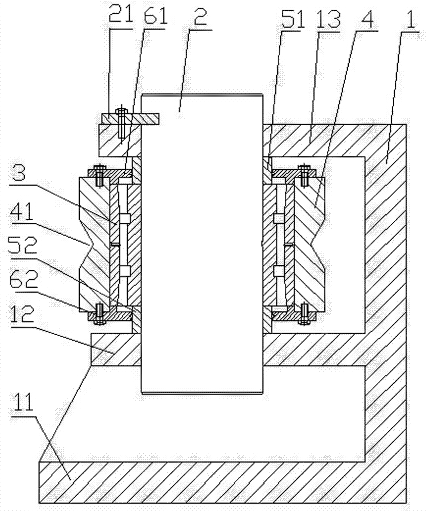
[0017] Such as figure 1 As shown, the limit wheel includes a base 1, a pin shaft 2, a double-row cylindrical roller bearing 3 and a roller 4. The base 1 is in a reverse "E" shape, and includes a bottom plate 11, a lower support plate 12 and an upper support from bottom to top. Plate 13, the base plate 11 is in direct contact with the ground, the lower support plate 12 and the upper support plate 13 have through holes of the same size and coaxial respectively; the pin shaft 2 passes through the through holes on the lower support plate 12 and the upper support plate 13 The part of the pin shaft 2 exposed from the upper support plate 13 has a slot for the shaft end baffle 21 to snap in. The diameter of the end surface of the shaft end baffle 21 is greater than the diameter of the through hole on the upper support plate 13, and the shaft end baffle 21 snaps in. into the slot of the pin shaft 2, and fixed on the upper support plate 13 with screws to prevent the pin shaft 2 from mov...
Embodiment 2
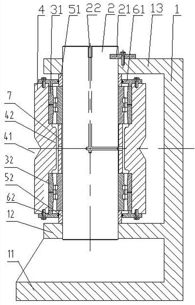
[0019] Such as figure 2 As shown, the limit wheel includes a base 1, a pin shaft 2, a double-row cylindrical roller bearing 3 and a roller 4, and the inner hole of the roller 4 is installed with a first double-row cylindrical roller bearing 31 and a second double-row cylindrical roller bearing 32. In order to support the facing outer ring end faces of the two bearings, so that the outer ring end faces of the two bearings continue to be clamped by the first transparent cover 61 and the second transparent cover 62, the inner wall of the roller 4 is provided with a The annular boss 42 that supports the end faces of the outer rings of the two bearings in one piece, in order to make the end faces of the inner rings of the two bearings continue to be clamped by the first stop ring 51 and the second stop ring 52, between the two bearings A spacer 7 is installed on the pin shaft 2 to support the end faces of the inner rings of the two bearings. The center of the pin shaft 2 is provid...
Embodiment 3
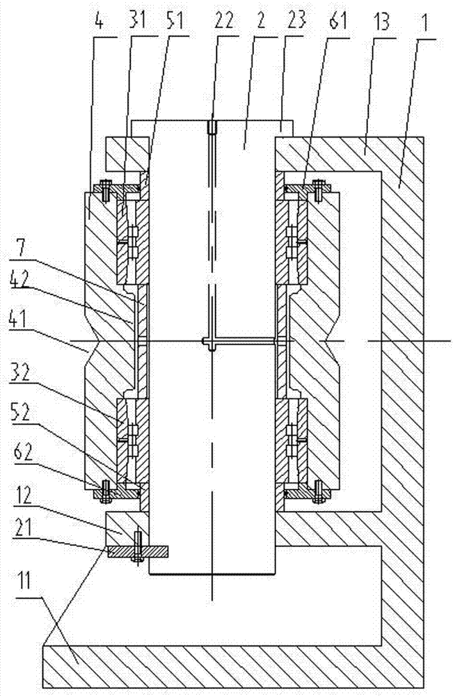
[0021] Such as image 3 As shown, the limit wheel includes a base 1, a pin shaft 2, a double-row cylindrical roller bearing 3 and a roller 4. The part of the pin shaft 2 protruding from the lower support plate 12 has a slot, and a shaft end baffle is arranged in the slot. 21. The shaft end baffle 21 is fixed on the lower support plate 12 with screws, that is to say, the pin shaft 2 is fixed on the lower support plate 12, and the part of the pin shaft 2 exposed to the through hole of the upper support plate 13 is provided with a cast The integral cap 23 can reduce the stress of the shaft end baffle 21 when the pin shaft has a tendency to move downward; the rest of the structure is the same as that of the first embodiment.
[0022] The working principle and usage method of the present invention are as Figure 4 As shown, there are two initially docked cylinders 8, which are divided into a first sub-cylinder 81 and a second sub-cylinder 82, and slopes are respectively opened on ...
PUM
 Abstract
Description
Claims
Application Information
 - R&D
- Intellectual Property
- Life Sciences
- Materials
- Tech Scout
- Unparalleled Data Quality
- Higher Quality Content
- 60% Fewer Hallucinations
Browse by: Latest US Patents, China's latest patents, Technical Efficacy Thesaurus, Application Domain, Technology Topic, Popular Technical Reports.
© 2025 PatSnap. All rights reserved.Legal|Privacy policy|Modern Slavery Act Transparency Statement|Sitemap|About US| Contact US: help@patsnap.com