Double-end double-drive double-horizontal-shaft mixer

A dual-drive, dual-horizontal shaft technology, applied in cement mixing devices, clay preparation devices, chemical instruments and methods, etc., can solve the problem of increasing the structural size and weight of the drive motor, uneven weight distribution at both ends of the mixer, and reducing the overall stability of the mixer. To reduce the size and weight of the structure, the weight distribution at both ends is even, and the structure is simple.

Inactive Publication Date: 2013-05-01
CHANGAN UNIV
View PDF3 Cites 2 Cited by
  • Summary
  • Abstract
  • Description
  • Claims
  • Application Information

AI Technical Summary

Problems solved by technology

The continuous increase in the power of the stirring drive motor directly leads to a significant increase in the structural size and weight of the drive motor, which leads to the installation space required by the drive motor on the end face of the mixing drum to be too large and cannot be arranged. Seriously uneven distribution of end weight reduces the overall stability of the mixer

Method used


Image

  • Double-end double-drive double-horizontal-shaft mixer
  • Double-end double-drive double-horizontal-shaft mixer
  • Double-end double-drive double-horizontal-shaft mixer

Examples


Embodiment 1

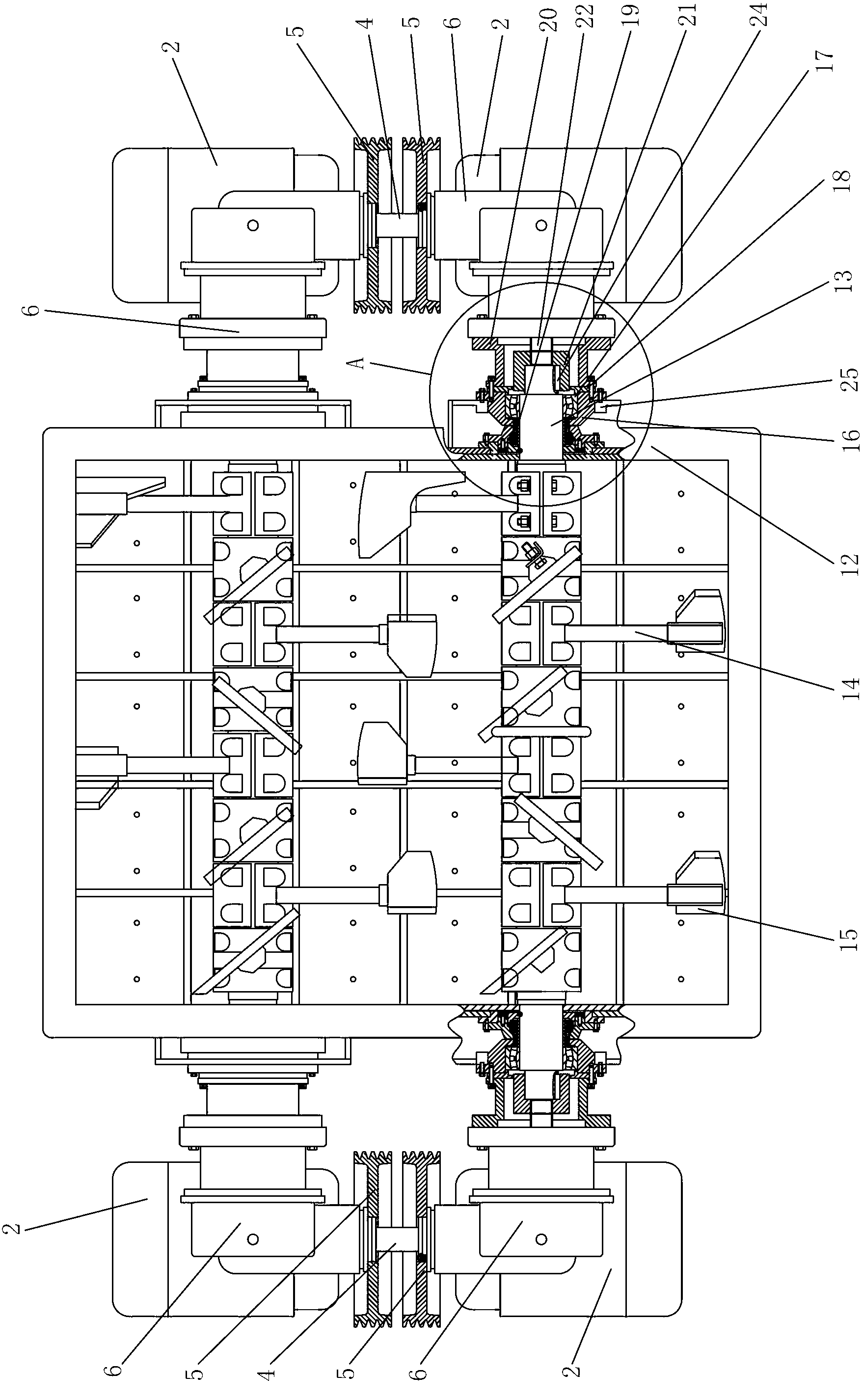
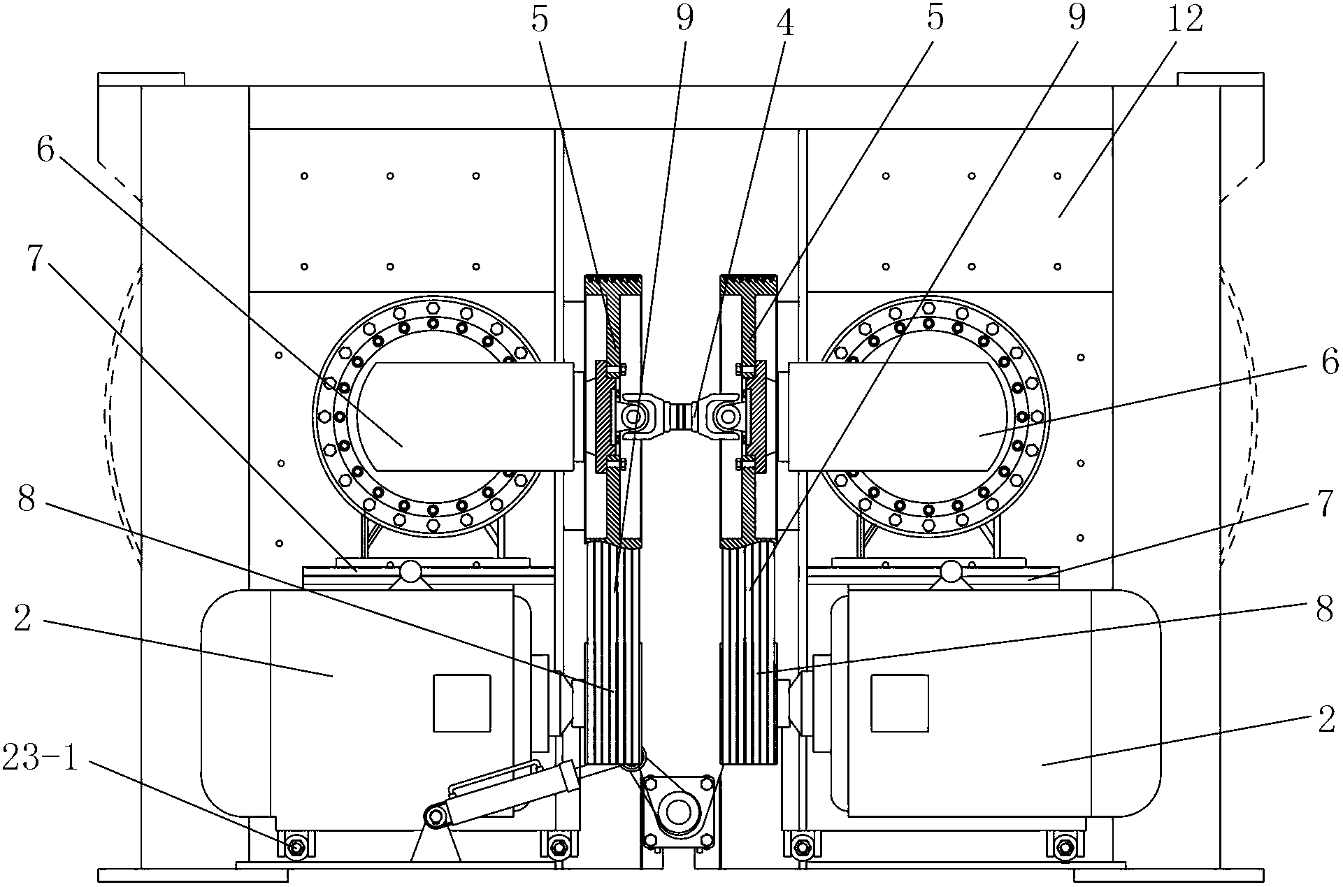
[0031] like Figure 1 to Figure 4 As shown, a double-end double-drive double-horizontal shaft mixer includes a mixing drum 12, two stirring shafts 13 arranged in parallel in the mixing drum 12, a stirring arm 14 installed on the stirring shaft 13, and a stirring arm 14 installed at the end of the stirring arm 14. The stirring blade 15 at the top and the driving motor 2 installed on the side wall of the end of the mixing drum 12 and the transmission assembly connecting the driving motor 2 and the stirring shaft 13, the stirring shaft 13 rotates through the stirring bearings 17 sleeved at its two ends Installed on the mixing drum 12, the stirring bearing 17 is supported by the stirring shaft bearing seat 16, and the number of the driving motors 2 is four, wherein two driving motors 2 are arranged on the left end side wall of the mixing drum 12, and the other two The drive motor 2 is arranged on the right side wall of the mixing drum 12, and the number of the transmission assembl...

Embodiment 2

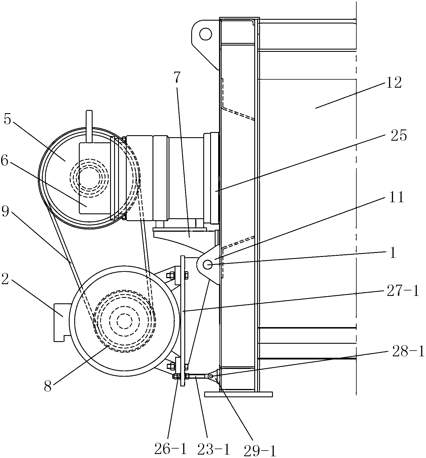
[0040] like Figure 5 to Figure 7 As shown, the difference between this embodiment and Embodiment 1 is that: the driving motor 2 is arranged above the speed reducer 6 , and the driving pulley 8 is arranged above the driven pulley 5 . In this implementation, preferably, a second belt adjustment tensioning device is also included, and the second belt adjustment tensioning device includes a second support stand 27-2, a second adjustment nut 26-2, a second support screw 23 -2 and the second hinged stand 29-2, the bottom of the drive motor 2 is fixed on the second support stand 27-2, the inner side of the drive motor 2 is connected to the side wall of the mixing drum 12 through the second pin 3 The lifting lug 11 on the top is hinged, the second support stand 27-2 is connected with one end of the second support screw 23-2 through the second adjustment nut 26-2, the other end of the second support screw 23-2 One end is hinged with the second hinged stand 29-2 through the second pin...


PUM


Abstract

The invention discloses a double-end double-drive double-horizontal-shaft mixer which comprises a mixing drum, two mixing shafts, mixing arms, mixing blades, four driving motors and four transmission assemblies, wherein the two driving motors are arranged on a side wall of the left end of the driving motor; the other two driving motors are arranged on a side wall of the right end of the mixing drum; the two transmission assemblies are arranged at the left end of the mixing drum; the other two transmission assemblies are arranged at the right end of the mixing drum; the two transmission assemblies located at the left end of the mixing drum are connected by a coupler; the two transmission assemblies located at the right end of the mixing drum are connected by a coupler; and each end of each mixing shaft is connected with one driving motor by one transmission assembly and driven by the driving motor. The configuration power of a single mixing driving motor is reduced, the structural sizes and weights of the driving motors are decreased, the transmission assemblies are convenient to arrange, and the overall structure of the mixer is more reasonable and stable.

Description

technical field [0001] The invention relates to a twin-shaft mixer, in particular to a double-end double-drive twin-shaft mixer. Background technique [0002] The twin-shaft mixer is the leading model widely used in concrete mixing equipment at present. It has the remarkable advantages of large capacity, high work efficiency and good mixing quality. It consists of parallel stirring shafts rotating in opposite directions and the stirring arms and stirring blades installed on them. [0003] The existing twin-shaft mixer generally adopts the form of single-end drive, which can be divided into two structures according to the nominal volume of the mixer: 1m 3 and 1m 3 The following twin-shaft mixers usually adopt the form of single-end single-motor drive and gear synchronization; 1m 3 The above generally adopt the form of single-ended dual-motor drive and coupling synchronization. For these single-end driven twin-shaft mixers, the drive motor is arranged at one end of the mix...

Claims


Application Information

Patent Timeline
Patent Type & Authority Applications(China)
IPC IPC(8): B28C5/08
Inventor 赵利军徐鹏杰余志龙冯忠绪翁军良潘旭磊张旭
Owner CHANGAN UNIV
Why Eureka
Try Eureka