Gear shift control device for hybrid vehicle drive system

A hybrid vehicle and drive system technology, applied in the direction of hybrid vehicles, power units, and engine-driven traction, can solve the problems of discontinuous shifting impact of driving torque, etc., to reduce shifting impact and suppress fluctuations Effect

Inactive Publication Date: 2013-05-01
AISIN SEIKI KK
View PDF6 Cites 5 Cited by
  • Summary
  • Abstract
  • Description
  • Claims
  • Application Information

AI Technical Summary

Problems solved by technology

In addition, when the motor-generator performs drive assist by adding the assist torque of the motor-generator to the engine torque in order to improve fuel economy when the state of charge of the battery is good, when the speed change operation is performed, it can be considered that the drive rotation Torque is discontinuous and can cause shift shock

Method used


Image

  • Gear shift control device for hybrid vehicle drive system
  • Gear shift control device for hybrid vehicle drive system
  • Gear shift control device for hybrid vehicle drive system

Examples


Embodiment Construction

[0027] The following will refer to Figure 1 to Figure 8 One embodiment of a transmission control device for a drive system of a hybrid vehicle is explained.

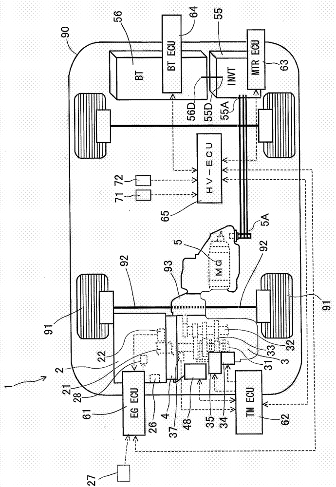
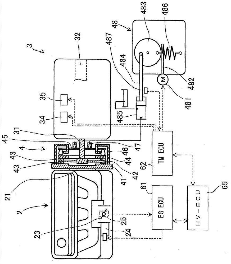
[0028] like figure 1 As shown, a hybrid vehicle drive system 1 is a front-engine, front-wheel-drive type (FF type) drive system, and an engine 2 serving as a drive source and a motor generator 5 are attached to a chassis The front portions of the wheels 90 are arranged in parallel so that the front drive wheels 91 are driven by either the engine 2 and the motor generator 5 or by both the engine 2 and the motor generator 5 simultaneously. A hybrid vehicle drive system 1 includes an automatic transmission 3 and a clutch 4 . exist figure 1 and figure 2 In , the dotted arrows connecting the elements show the flow of control.

[0029] like figure 1 As shown, the engine 2 is arranged transversely on the chassis 90 on the opposite front side of the axle 92 of the front drive wheels 91 . The engine 2, the clutch 4, and ...


PUM


Abstract

A gear shift control device for controlling a hybrid vehicle drive system (1) including an engine (2), an automated transmission (3), a clutch (4), and a motor generator (5), includes a torque indication means for indicating a driver request torque (Tdrv) determined in accordance with an operation amount of an accelerator operated by a driver, a power generation interruption means changing a vehicle state to an engine driven state using all of the engine torque (Te) when a preliminary gear shift condition is satisfied in a state where the engine (2) drives a driving wheel (91) and the motor generator (5) is actuated to generate an electric power, a gear shift control means reducing the engine torque (Te) and generating an assist torque (Tast) by actuating the motor generator (5), disconnecting the clutch (4), and returning the clutch (4) to a connected state after changing gear sets of the gear train when a gear shift condition of the automated transmission (3) is satisfied.

Description

technical field [0001] The present application generally relates to a gear shift control device for a hybrid vehicle drive system. Background technique [0002] With the widespread use of hybrid vehicles, various known drive systems for hybrid vehicles including an engine and an electric motor as drive sources are put into practical use. For example, according to a known structure, an input shaft of an automated transmission is connected to an output shaft of an engine via a clutch, and an electric motor is connected between the output shaft of the automatic transmission and driving wheels. According to the aforementioned configuration, a motor generator (which is a motor having a power generating function) is mostly used as the motor, so that a separate generator is not required to supply power. Also, for example, an automated manual transmission (AMT) is a manual transmission that selectively engages one of a plurality of sets of gears and is automatically operated by an ...

Claims


Application Information

Patent Timeline
Patent Type & Authority Applications(China)
IPC IPC(8): B60W20/00B60W10/111B60W10/02B60W10/08B60W10/06F16H61/04B60L50/16
CPCB60K2006/4808B60Y2200/92B60W30/19Y02T10/6286B60W20/00B60W10/06B60W10/08F16H61/04F16H63/502B60W10/02F16H2061/0433B60W10/11Y02T10/62B60K6/543B60W20/40B60W20/30B60W2510/0657
Inventor 寺川智充细井泰宏北村雄一郎铃木良英上田克则吉田茂之平尾俊一
Owner AISIN SEIKI KK
Why Eureka
Try Eureka