
Reaction chamber

A reaction chamber and cavity technology, applied in the field of reaction chambers, can solve problems such as easy damage of rotating structures

Inactive Publication Date: 2013-05-01
BRILLIANT LIGHT TECH
View PDF4 Cites 5 Cited by
  • Summary
  • Abstract
  • Description
  • Claims
  • Application Information

AI Technical Summary

Problems solved by technology

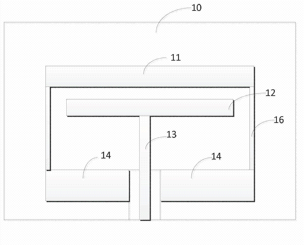
[0005] The object of the present invention is to provide a reaction chamber to solve the problem that the rotating structure in the existing reaction chamber is extremely easy to damage

Method used


Image

  • Reaction chamber
  • Reaction chamber

Examples


Embodiment Construction

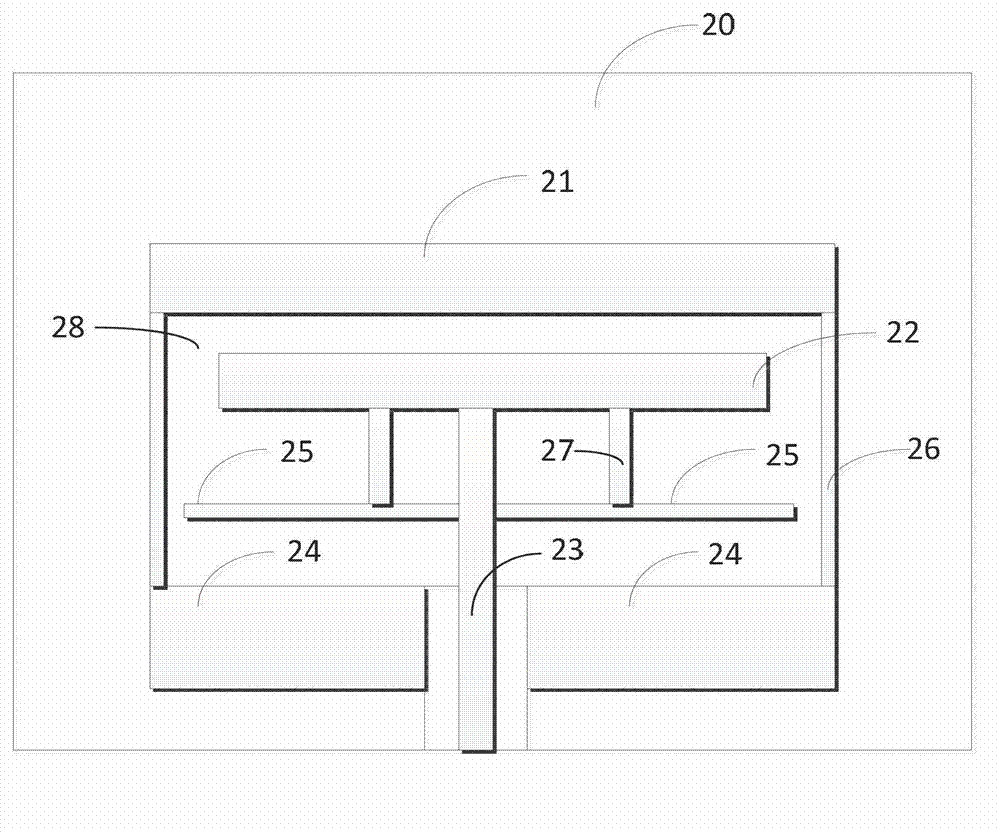
[0023] The reaction chamber proposed by the present invention will be further described in detail below with reference to the accompanying drawings and specific embodiments. Advantages and features of the present invention will be apparent from the following description and claims. It should be noted that all the drawings are in a very simplified form and use imprecise scales, and are only used to facilitate and clearly assist the purpose of illustrating the embodiments of the present invention.

[0024] In the reaction chamber of the prior art, the rotating structure is usually damaged before reaching its designed service life, thereby greatly increasing the maintenance investment of the equipment. And for this problem, those skilled in the art have never found out its root cause. That is to say, the problem that the rotating structure in the existing reaction chamber is extremely fragile has puzzled those skilled in the art for a long time, and the existence of this problem...


PUM


Abstract

The invention provides a reaction chamber which comprises a chamber body, a tray in the former, a rotary structure in the chamber body, a heater arranged in an accommodating space to heat the tray, and a heat insulation structure in the accommodating space, wherein the rotary structure is connected with the tray through a cylindrical side wall, and the rotary structure, the tray and the cylindrical side wall form the accommodating space; and with the heat insulation structure, the heat exchange between the heater and the rotary structure can be at least reduced. According to the reaction chamber, the rotary structure low has probability of damage, and is longer in service life, which reduces the equipment maintenance investment.

Description

technical field [0001] The invention relates to the technical field of integrated circuit equipment, in particular to a reaction chamber. Background technique [0002] Metal organic chemical vapor deposition (MOCVD) is a chemical vapor deposition process developed on the basis of vapor phase epitaxy (VPE). It uses organic compounds of group III and group II elements and hydrides of group V and group VI elements as reaction gases for crystal growth, and conducts epitaxial deposition process on sapphire substrate or other substrates by thermal decomposition reaction method to grow various Epitaxial material layers of III-V, II-VI compound semiconductors and their multiple solid solutions. [0003] Please refer to figure 1 , which is a structural schematic diagram of a reaction chamber of an MOCVD device in the prior art. Such as figure 1 As shown, the reaction chamber 1 includes a chamber body 10; a tray 11 disposed in the chamber body 10, the tray 11 is used to carry semi...

Claims


Application Information

Patent Timeline
IPC IPC(8): C23C16/44
Inventor 黄允文李王俊
Owner BRILLIANT LIGHT TECH
Learn More