Automatic matching injection tubular column for injecting air and steam

A technology of air and steam injection, applied in drilling pipes, casings, production fluids, etc., can solve the problems of inability to form large-scale production, unbalanced well soaking in the steam injection layer, and increased heat loss in the first steam injection layer. The effect of uneven production of oil layer, improvement of suction profile and increase of production layer

Active Publication Date: 2013-05-01
PETROCHINA CO LTD
View PDF10 Cites 13 Cited by
  • Summary
  • Abstract
  • Description
  • Claims
  • Application Information

AI Technical Summary

Problems solved by technology

[0003] First, because steam cannot be injected into two layers at the same time, it can only be injected into the lower layer or the upper layer first, which will inevitably lead to unbalanced wells in the steam injection layer, which will increase the heat loss of the first steam injection layer and deteriorate the thermal recovery effect;
[0004] Second, since the steam injection volume of the upper and lower floors is achieved by artificial wellhead pitching, in some cases, due to human error, the error between the actual steam injection volume of the upper and lower floors and the design steam injection volume is relatively large;
[0005] Third, when layering the balls, the hot injection furnace needs to be emptied, so every time the balls are added, the steam will be wasted
[0006] Fourth, during steam injection, the injection is realized by throwing balls at the wellhead of thermal recovery. Due to the high temperature and high pressure at the wellhead, there are major unsafe risks in the operation, and it also increases the labor intensity of the operators.
[0008] ① The structure is unreasonable, and the distribution of injected gas (steam) volume is not accurate. Due to the different gas absorption capacity of the formation, the distributed gas (steam) volume is different. The distribution of gas (steam) volume is not only related to the area of ​​gas (steam) injection It is also related to the injection pressure and the gas (steam) capacity of the formation
[0009] ② At the beginning of gas (steam) injection, due to the low pressure in the well, the flow rate of the injected gas (steam) liquid mixture is too fast, causing the adjustment valve to close the injection channel, resulting in the failure of gas (steam) injection
[0010] ③The existing gas (steam) distribution device cannot be used in batches due to unreasonable design. The design of the gas (steam) volume should be scheduled for operation within ten days, and the construction can be carried out immediately after the scheduling, and the gas (steam) distribution device cannot be processed immediately, so that the quantitative injection of heavy oil wells cannot be implemented on a large scale;
[0012] ①According to the analysis of its working principle, due to the different pressures between the layers of the formation, the air (steam) capacity of each layer is different, and the steam injection volume is distributed only by the area of ​​the gas (steam) hole, and there is a certain difference in the steam volume distribution. error
[0013] ② Its working principle is to distribute the steam injection amount according to the area of ​​the steam injection hole, so only after the well is selected, the steam (steam) amount of each layer is processed, which may delay the on-site construction due to insufficient processing time , so it cannot be mass-produced
[0014] ③Due to design problems, at the initial stage of gas (steam) injection in oil wells, the piston is adjusted to close the steam injection hole under the action of high-speed, high-pressure gas (steam)-liquid mixture, and steam injection cannot be realized, wasting a lot of manpower and material resources

Method used


Image

  • Automatic matching injection tubular column for injecting air and steam
  • Automatic matching injection tubular column for injecting air and steam
  • Automatic matching injection tubular column for injecting air and steam

Examples


Embodiment Construction

[0034] The following will clearly and completely describe the technical solutions in the embodiments of the present invention with reference to the accompanying drawings in the embodiments of the present invention. Obviously, the described embodiments are only some, not all, embodiments of the present invention. Based on the embodiments of the present invention, all other embodiments obtained by persons of ordinary skill in the art without making creative efforts belong to the protection scope of the present invention.

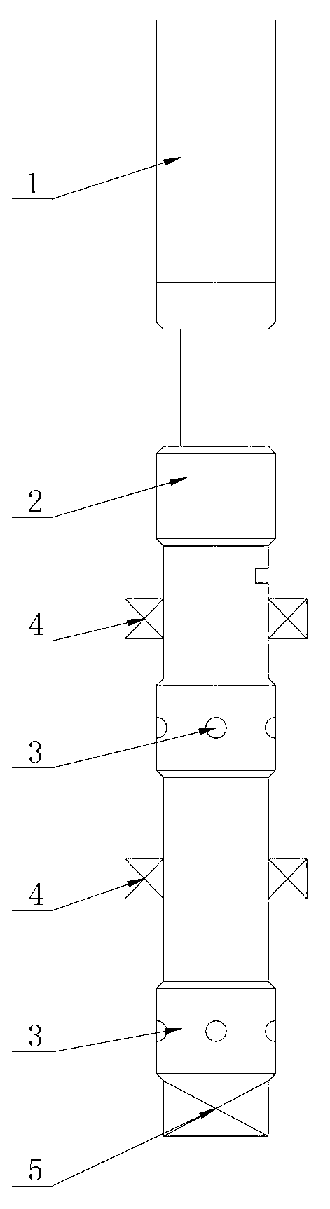
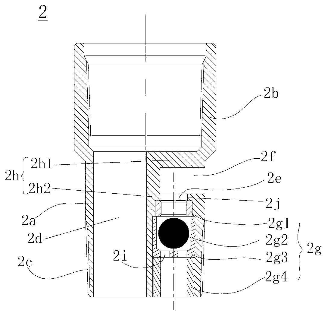
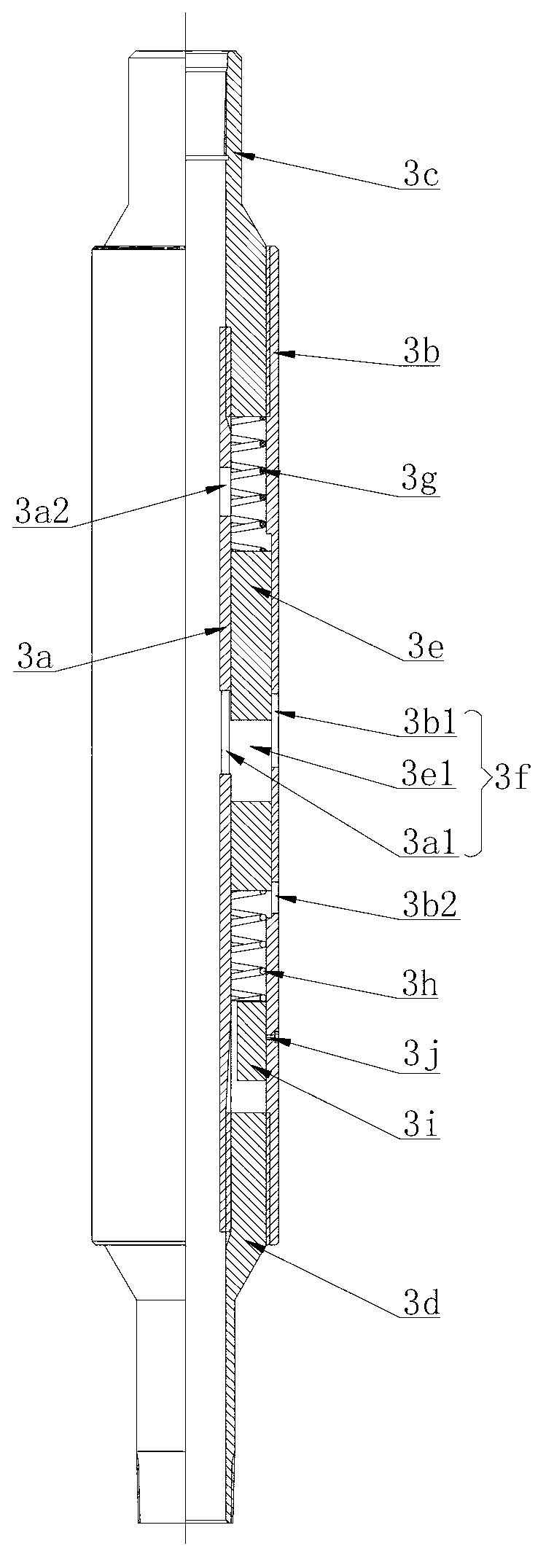
[0035] like Figure 1 to Figure 3 As shown, the automatic air and steam injection string proposed by the embodiment of the present invention includes a telescopic tube 1 , a safety steering valve 2 , a quantitative injection valve 3 and a thermal recovery packer 4 . The upper end of the safety steering valve 2 is connected with the telescopic tube 1 . The upper end of the thermal recovery packer 4 is connected with the lower end of the safety steering valve 2...


PUM


Abstract

The invention discloses an automatic matching injection tubular column for injecting air and steam, which comprises an extension tube, a safety conversion valve and a thermal recovery packer, wherein the upper end of the safety conversion valve is connected with the extension tube; the upper end of the thermal recovery packer is connected with the lower end of the safety conversion valve by screw thread, and the lower end of the thermal recovery packer is connected with the upper end of a quantitative dispensing valve by screw thread; the lower end of the quantitative dispensing valve is plugged by a screwed plug; the quantitative dispensing valve comprises an internal lining sleeve, an outer sleeve, an upper joint, a lower joint, a sliding sleeve and an air injection channel, wherein the outer sleeve is sheathed outside the internal lining sleeve; the upper joint and the lower joint are respectively arranged at the upper end and the lower end of the quantitative dispensing valve, and respectively arranged between the outer sleeve and the internal lining sleeve; the sliding sleeve is arranged between the outer sleeve and the internal lining sleeve; the sliding sleeve is arranged between the upper joint and the lower joint in a way of moving up and down; the internal lining sleeve, the outer sleeve and the sliding sleeve are respectively provided with a corresponding air injection hole, and the air injection channel is formed by the air injection holes; and the area of the air injection channel is changed along with the up and down movement of the sliding sleeve.

Description

technical field [0001] The invention relates to a gas injection (steam) pipe column in the field of air injection catalytic oxidation mining of heavy oil, in particular to an automatic selection and matching injection pipe column for air injection and steam. Background technique [0002] At present, the air injection catalytic oxidation oil recovery technology of heavy oil has been applied in Liaohe Oilfield and has achieved relatively satisfactory production results. The air injection catalytic oxidation oil recovery technology is an important supplementary method for the lack of energy in the formation. At present, air injection oil recovery mainly adopts a general gas injection method, and different oil layers have different gas absorption capabilities, resulting in uneven producing layers of oil reservoirs and affecting the recovery effect of crude oil. At present, the layered injection technology mainly adopts the matching technology of packer and injection valve (ball ...

Claims


Application Information

Patent Timeline
Patent Type & Authority Applications(China)
IPC IPC(8): E21B43/16E21B43/24E21B17/00E21B34/14
Inventor 王书慧王玉龙管九洲郎宝山吴非张鸿璐刘昌龙
Owner PETROCHINA CO LTD
Why Eureka
Try Eureka