Double-ejection rod ring magnetic steel piston magnetorheological damper

A magnetorheological damper, annular piston technology, applied in vibration suppression adjustment, non-rotation vibration suppression, etc., can solve the problems of limited application range, low viscosity of magnetorheological fluid, small damping force, etc., to increase the effective working area , Solve the effect of small working stroke and large damping force

Inactive Publication Date: 2015-05-27
CHINA UNIV OF MINING & TECH
View PDF6 Cites 0 Cited by
  • Summary
  • Abstract
  • Description
  • Claims
  • Application Information

AI Technical Summary

Problems solved by technology

[0003] Magneto-rheological damper is an intelligent damping device, its damping force can be remotely adjusted steplessly by controlling the power supply, but the adjustment process consumes electric energy. When the output current of the ordinary magnetorheological damper is zero, The viscosity of the magnetorheological fluid reaches the lowest and the damping force generated is small. Therefore, once the control power supply fails, the damping force of the ordinary magnetorheological damper is difficult to ensure the normal operation of the system due to the small output; the magnetorheological damper The output damping force is also related to the effective working area between the working cylinder and the piston. Because the stroke of the existing single-rod damper is small, the piston of the double-rod damper is mostly cylindrical, and the working cylinder is cylindrical. The effective area of ​​the piston and the working cylinder is small, the damping force generated is small, and the application range is greatly limited

Method used


Image

  • Double-ejection rod ring magnetic steel piston magnetorheological damper
  • Double-ejection rod ring magnetic steel piston magnetorheological damper
  • Double-ejection rod ring magnetic steel piston magnetorheological damper

Examples


Embodiment Construction

[0014] The present invention will be further described below in conjunction with accompanying drawing.

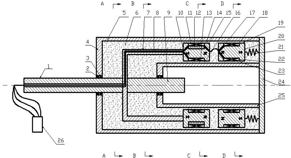
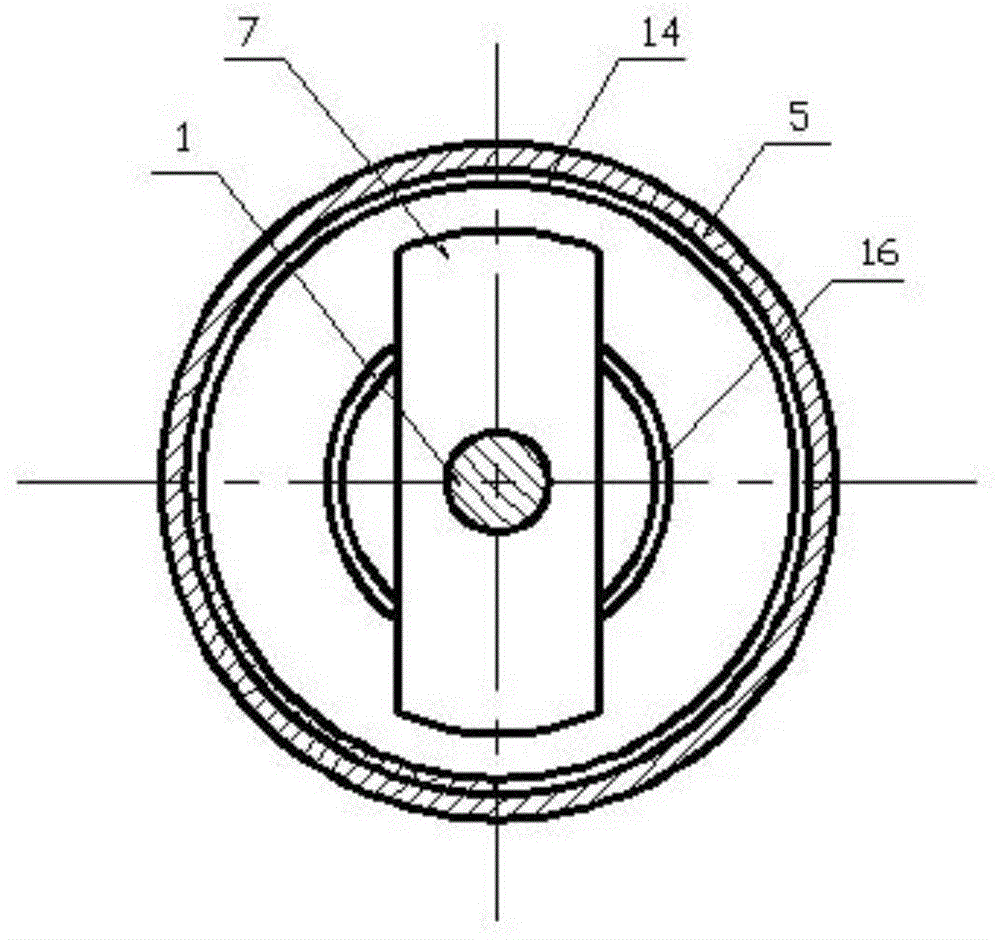
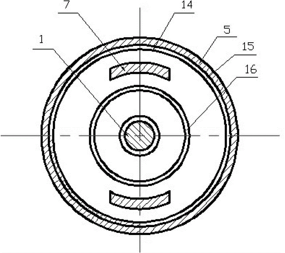
[0015] Such as Figure 1 to Figure 5 As shown, the magnetorheological damper with double-rod annular magnetic steel piston includes an outer working cylinder 5, a U-shaped bracket 7, an annular piston 15 and a piston rod 1, and the outer working cylinder 5 is filled with magnetorheological fluid 6, The two ends of the outer working cylinder 5 are sealed by the left end cover 4 and the right end cover 24, and a center hole is arranged on the left end cover 4, and a bearing 2 and a sealing device 3 are installed in the center hole, and one end of the piston rod 1 passes through the center hole and is placed. Outside the outer working cylinder 5, the other end is connected to the center of the bottom of the U-shaped bracket 7, and one end of the U-shaped bracket 7 is connected to the left end of the annular piston 15. Inside the annular piston 15, there are inner surrounding s...


PUM


Abstract

The invention discloses a double-ejection rod ring magnetic steel piston magnetorheological damper. The damper comprises a gain ring piston (20), a gain piston rod (9), a spring (21) and an inner cylinder (25); an outer working cylinder (5) and the inner cylinder (25) form a double-layered cylinder structure, both a ring piston (15) and the gain ring piston (20) are installed between the outer working cylinder (5) and the inner cylinder (25), one end of the gain piston rod (9) is installed on a U-shaped support (7), the other end of the gain piston rod (9) is installed on the inner cylinder (25), a right end cover (24) is connected with the spring (21), and the left end of the spring (21) is connected with the right end of the gain ring piston (20). The damper not only has the advantages of long working stroke and low consumption during a working process, but also can have a safety protection function, so that the service life of a part is prolonged.

Description

technical field [0001] The invention relates to a magneto-rheological fluid damper, in particular to a magneto-rheological damper with double-outlet rod ring magnet steel pistons. Background technique [0002] Magnetorheological fluid is a new type of magnetic functional material. When there is no external magnetic field, it behaves as a well-flowing Newtonian fluid. However, under the action of an external magnetic field, the rheological properties of the fluid change dramatically, showing mechanical properties similar to solids. And the viscosity change is continuous and reversible, that is, once the magnetic field is removed, it becomes a flowable liquid again. The continuous, reversible, rapid and easy-to-control characteristics of magnetorheological fluid effects make magnetorheological fluid mechanical devices have very wide application prospects in aviation, aerospace, automobile industry, hydraulic transmission, biotechnology, medical treatment and other fields. [...

Claims


Application Information

Patent Timeline
Patent Type & Authority Patents(China)
IPC IPC(8): F16F9/53
Inventor 刘新华陈庆庆路和王冬冬刘永志刘浩
Owner CHINA UNIV OF MINING & TECH
Why Eureka
Try Eureka