Displacement detecting device

一种位移检测、位移的技术,应用在垂直向的位移领域,达到简化使用条件的效果

Active Publication Date: 2013-05-01
DMG MORI CO LTD
View PDF7 Cites 15 Cited by
  • Summary
  • Abstract
  • Description
  • Claims
  • Application Information

AI Technical Summary

Problems solved by technology

With this method, the measurement range is widened and good linearity can be achieved; however, when the measurement range is widened, the measurement is affected by changes in the wavelength of the light source and changes in the refractive index of air

Method used


Image

  • Displacement detecting device
  • Displacement detecting device
  • Displacement detecting device

Examples


Embodiment Construction

[0048] Displacement detection devices according to various embodiments of the present invention will refer to Figure 1 to Figure 31 Described below. It should be noted that similar components are designated by similar reference numerals in the drawings. It should also be noted that the present invention is not limited to the following embodiments.

[0049] It should also be noted that each of the various lenses described below may be a single lens or a lens group.

[0050] 1. The displacement detecting device according to the first embodiment

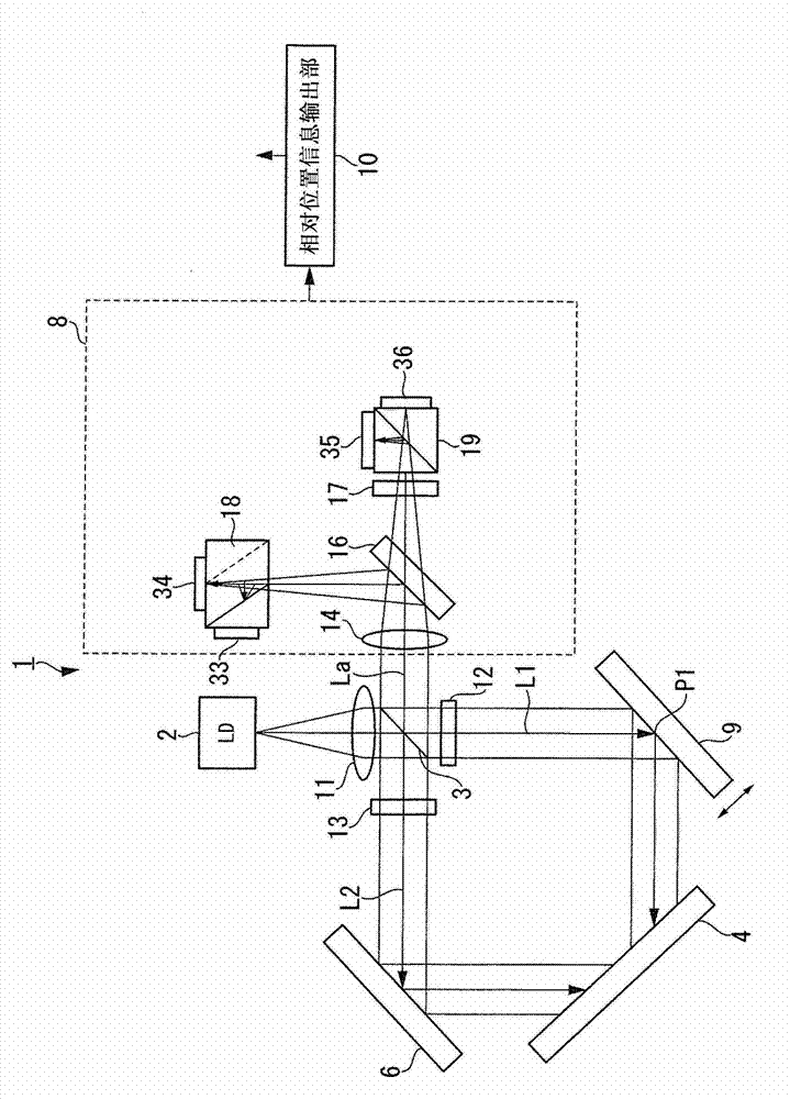
[0051] First, refer to Figure 1 to Figure 5 The configuration of a displacement detection device according to a first embodiment of the present invention (hereinafter referred to as “the present embodiment”) is described below.

[0052] 1-1. Construction example of displacement detection device

[0053] figure 1 is a diagram schematically showing the configuration of the displacement detection device 1, figure 2 is a side view...


PUM


Abstract

The invention relates to a displacement detecting device. A displacement detecting device (1) includes a light source (2), a beam splitting section (3), a diffraction grating (4), a reflecting section (6), a beam combining section (3), a light receiving section (8), and a relative position information output section (10). The diffraction grating (4) is adapted to diffract a first beam (L1) reflected by a surface-to-be-measured of a member-to-be-measured (9), and cause the diffracted first beam (L1) to be incident again on the surface-to-be-measured. The reflecting section (6) is adapted to reflect a second beam (L2) split by the beam splitting section to the beam splitting section (3). The light receiving section (8) is adapted to receive interfering light of the first beam (L1) and the second beam (L2). The relative position information output section (10) is adapted to output displacement information of the surface-to-be-measured in the height direction based on intensity of the received interfering light.

Description

[0001] Cross References to Related Applications [0002] The present invention encompasses subject matter related to Japanese Patent Application JP 2012-018715 filed in the Japan Patent Office on Jan. 31, 2012, the entire content of which is hereby incorporated by reference. technical field [0003] The present invention relates to a displacement detection device that detects displacement of a surface to be measured by a non-contact sensor using light emitted from a light source. More specifically, the present invention relates to techniques for detecting vertical displacement of a surface to be measured. Background technique [0004] Conventionally, a displacement detection device that detects the displacement and shape of a surface to be measured by light in a non-contact manner is widely used. As a typical example, there is a method in which laser light is irradiated on a surface to be measured, and a position change of reflected light is detected by PSD. However, this ...

Claims


Application Information

Patent Timeline
Patent Type & Authority Applications(China)
IPC IPC(8): G01B11/02G01B9/02
CPCG01B9/02081G01B9/02022G01B9/00G01B9/02015G01B9/02018G01B2290/70G01B9/02G01B11/00
Inventor 田宫英明
Owner DMG MORI CO LTD
Why Eureka
Try Eureka