Comb-shaped slow-wave structure for multi-band electron beam channel

A strip-shaped electronic and slow-wave structure technology, which is applied to the circuit components of time-of-flight electron tubes, can solve the problems of lack of high power and low cost, so as to improve the efficiency of injecting wave interaction, increase output power, and improve The effect of operating current

Active Publication Date: 2013-05-01
HEFEI UNIV OF TECH
View PDF3 Cites 14 Cited by
  • Summary
  • Abstract
  • Description
  • Claims
  • Application Information

AI Technical Summary

Problems solved by technology

In the current THz research field, the lack of high-power, low-cost and portable room temperature THz light source is the most important factor limiting the application of modern THz

Method used


Image

  • Comb-shaped slow-wave structure for multi-band electron beam channel
  • Comb-shaped slow-wave structure for multi-band electron beam channel
  • Comb-shaped slow-wave structure for multi-band electron beam channel

Examples


Embodiment Construction

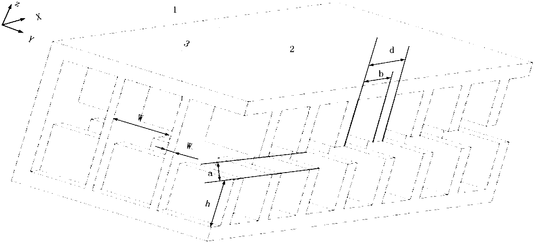
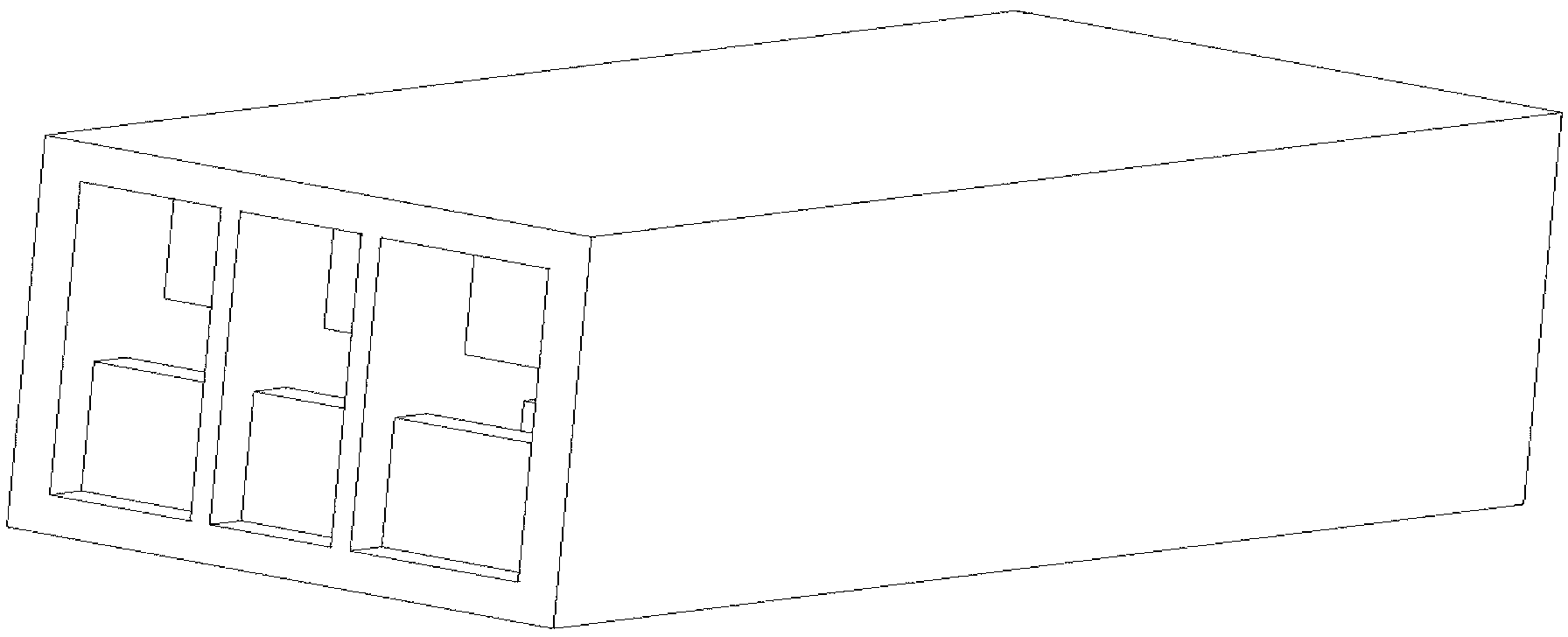
[0026] As shown in Figure 1, a comb-shaped slow-wave structure with multiple strip electron beam channels includes a rectangular waveguide wall 1 with open ends. The inner wall of the lower end of the rectangular waveguide wall 1 is staggered with double rows of comb-shaped teeth 2 , The rectangular waveguide wall 1 is inserted with n inserts 3 at equal intervals; the origin is the lower left corner of the front end of the rectangular waveguide wall 1 with open ends to establish XYZ three-dimensional coordinates, the origin is vertical upward as the Z axis, and the origin horizontal to the left is Y The axis, the origin horizontally and backward is the X axis, each tooth 2 is equally spaced and parallel to the YZ plane, and each insert 3 is parallel to the XZ plane.

[0027] The distance between the upper row of teeth and the lower row of double-row comb-shaped teeth is left as a strip electron injection flight path. The teeth 2 are rectangular, the insert 3 is a metal sheet, and ...


PUM


Abstract

The invention discloses a comb-shaped slow-wave structure for a multi-band electron beam channel. The comb-shaped slow-wave structure for the multi-band electron beam channel comprises a rectangular wave guide wall of which the two ends are open; double rows of comb-shaped teeth are arranged on the inner walls of the upper end surface and the lower end surface of the rectangular wave guide wall in a staggered way; a plurality of insertion pieces are inserted into the rectangular wave guide wall at equal intervals; XYZ three-dimensional coordinates are established by taking the lower-left corner of the front end surface of the rectangular wave guide wall of which the two ends are open as an original point; the direction which is upwards vertical to the original point is the Z-axis; the direction which is leftwards horizontally is the Y-axis; the direction which is backwards horizontally is the X-axis; the teeth are at equal intervals and are parallel to the YZ plane; and the insertion pieces are parallel to the XZ plane. The comb-shaped slow-wave structure for the multi-band electron beam channel has a simple main structure, is easy to machine and is compatible with the modern micro electronic mechanical system (MEMS) technology; a transverse edge effect of the comb teeth can be ignored; the working frequency band is widened obviously; the beam-wave interaction efficiency is high; the working current is improved; the output power is increased; and the comb-shaped slow-wave structure is a novel slow-wave structure which extremely has application potential.

Description

Technical field [0001] The invention relates to a comb-shaped slow-wave structure with multiple strip-shaped electron beam channels, belonging to the field of terahertz (THz) vacuum electronic devices. Background technique [0002] The generation of THz waves is a key link in the development of THz technology. According to the mechanism of terahertz radiation, its radiation sources can be divided into two categories: optical methods and electronic methods. In the current THZ research field, the lack of high-power, low-cost, and portable room temperature terahertz light sources is the most important factor limiting modern terahertz applications. [0003] The SP super-radiation produced by the periodic cluster has the characteristics of high radiation power and high spectral purity, and is an effective way to increase the output power of THz source devices. The method of obtaining periodic bunches has therefore become a major research hotspot in the development of THz s...

Claims


Application Information

Patent Timeline
Patent Type & Authority Applications(China)
IPC IPC(8): H01J23/24
Inventor 杨军李浩光李娇娇阮久福邓光晟尹治平吕国强蔡斐
Owner HEFEI UNIV OF TECH
Why Eureka
Try Eureka