Function conversion device for kitchen electrical appliance

A technology for kitchen appliances and conversion devices, which is applied to contact operating parts, cabinets, cabinets, and drawer parts, etc., can solve the problems of high manufacturing, low production and assembly efficiency, complex structure, etc., and achieves easy operation, The effect of fewer assembly steps and accurate positioning

Active Publication Date: 2013-05-01
ZHEJIANG SHAOXING SUPOR DOMESTIC ELECTRICAL APPLIANCE CO LTD
View PDF6 Cites 3 Cited by
  • Summary
  • Abstract
  • Description
  • Claims
  • Application Information

AI Technical Summary

Problems solved by technology

[0005] In order to overcome the defects of complex structure, high manufacturing cost and low production and assembly efficiency in the prior art, the present invention provides a functional conversion device for kitchen appliances with simple structure, convenient assembly, low manufacturing cost and accurate positioning

Method used


Image

  • Function conversion device for kitchen electrical appliance
  • Function conversion device for kitchen electrical appliance
  • Function conversion device for kitchen electrical appliance

Examples


Embodiment 1

[0039] Figure 1-9 An example of the function switching device for kitchen appliances according to the first embodiment of the present invention is illustrated in .

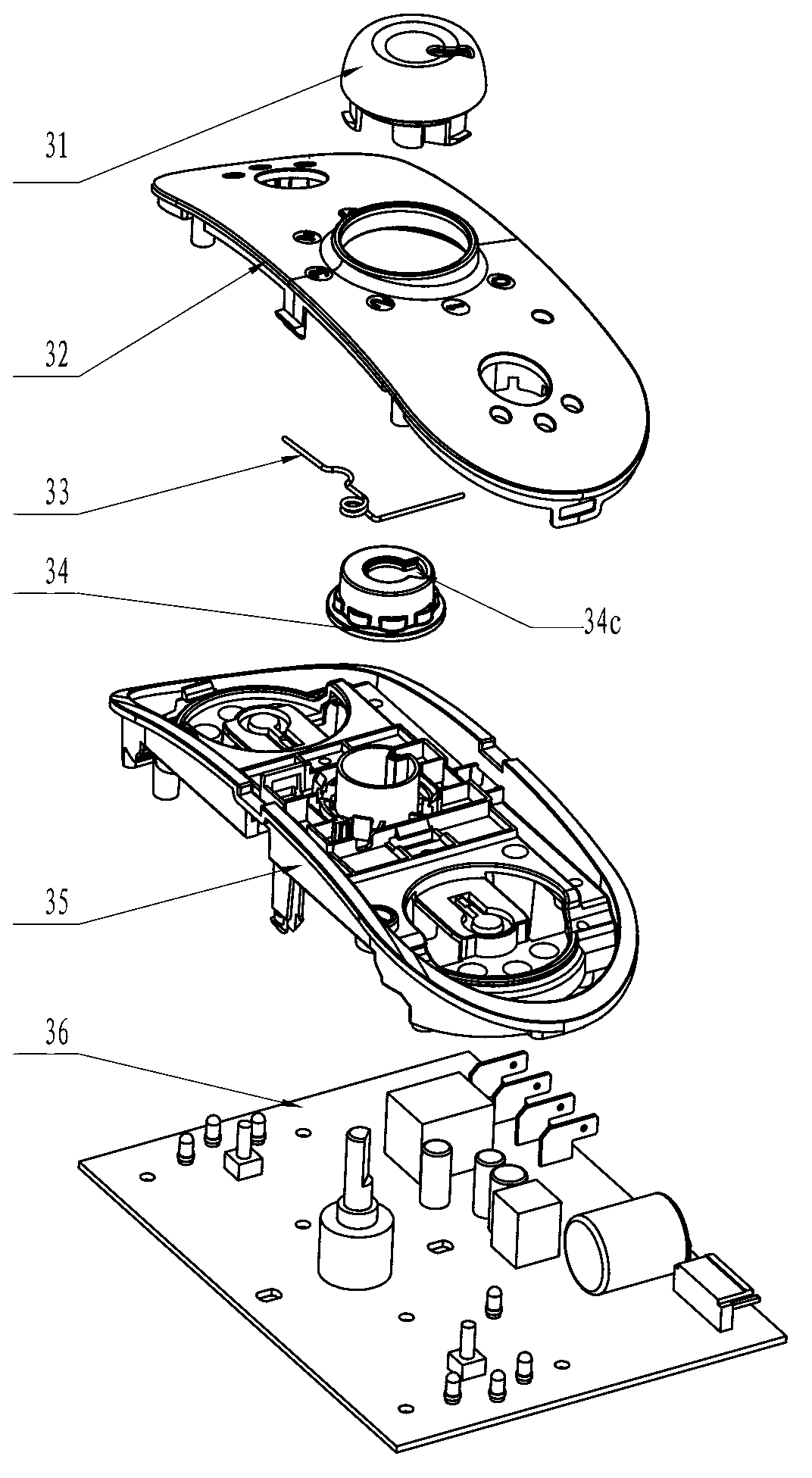
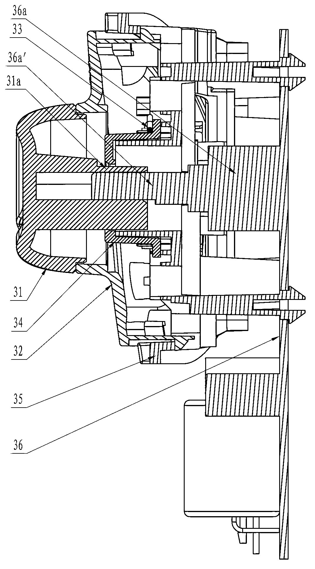
[0040] figure 1 shows a function conversion device for kitchen appliances, including a circuit board 36 for controlling the kitchen appliance, a potentiometer 36a arranged on the circuit board and electrically connected to it, and a control panel 32 arranged on the casing of the kitchen appliance , The potentiometer 36a has an operating portion 36a' for manipulation.

[0041] The function conversion device for kitchen appliances is also provided with a support base frame 35 made of insulating material, on which a first positioning element 34 , a control element 31 , and a second positioning element 33 are arranged.

[0042] The control panel 32 and the support base 35 are snap fit in a releasable manner.

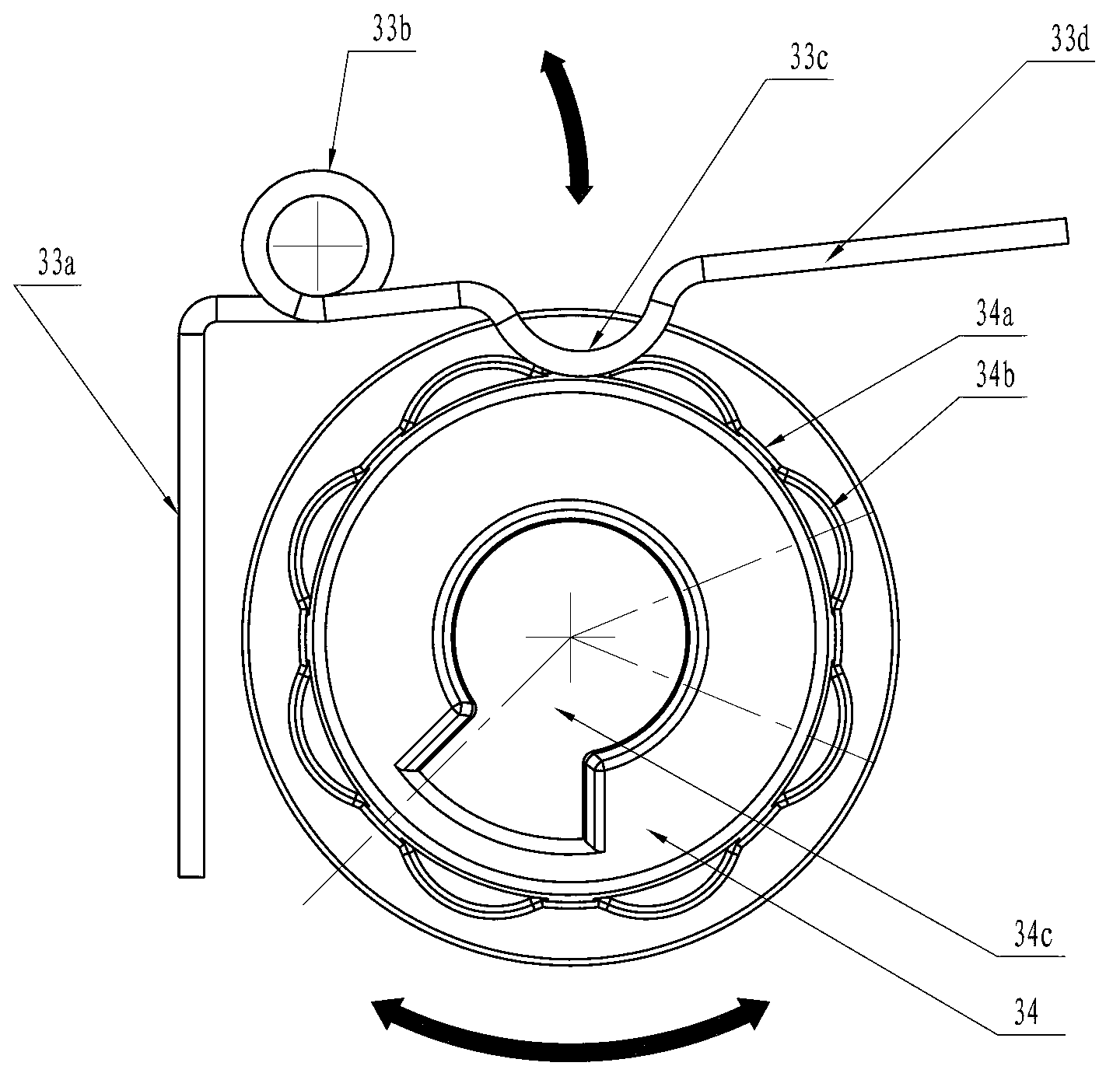
[0043] The first positioning element 34 is provided with a first positioning portion 34a, and the second ...

Embodiment 2

[0061] As another implementation mode, the stop safety in this embodiment can be provided on the control panel, which can be realized by setting a stop protrusion on the control panel to prevent the further rotation of the knob, and the rest is the same as that of the first embodiment.

Embodiment 3

[0062] Embodiment 3 Both ends of the shrapnel are fixed on the buckle of the bracket shrapnel formed integrally with the seat body. The positioning lobes of the shrapnel are in contact with the positioning protrusions or positioning grooves, and accurate positioning can be achieved by relying on the pressing force of the shrapnel locating lobes.

[0063]


PUM


Abstract

The invention relates to a function conversion device for a kitchen electrical appliance, belonging to the technical field of control switches. The function conversion device comprises a circuit board, a potentiometer which is arranged on the circuit board, and a control panel which is arranged on a kitchen electrical appliance shell. The potentiometer is provided with an operating part which is used for operation. The function conversion device additionally comprises a supporting bed frame. A first positioning element, an operating element and a second positioning element 33 are arranged on the supporting bed frame. A first positioning part is arranged on the first positioning element. A second positioning part is arranged on the second positioning element. The first positioning element and the second positioning element are matched with each other through bonding between the first positioning part and the second positioning part. The operating element is simultaneously bonded with the operating part of the potentiometer and the first positioning element to drive the operating part of the potentiometer and the first positioning element to move correspondingly. The function conversion device for the kitchen electrical appliance has the advantages that the structure is simple, the device is convenient to assemble, the manufacturing cost is low, the device is convenient to operate, the positioning accuracy is high, the expression is consistent with the function menu of the control panel and the operation of a user is facilitated.

Description

technical field [0001] The invention belongs to the technical field of household kitchen appliance control switches, and in particular relates to a function conversion conversion device. Background technique [0002] At present, most commercially available household kitchen appliances use function changeover switches to be controlled by potentiometers, which mainly detect the voltage on the LCD screen through the integrated circuit IC, and use light-emitting diodes (LEDs) to distinguish function menus to achieve precise positioning. At present, the mainstream method in the small household appliance market, but the cost of the control method is too high, the utilization rate after scrapping is low, and the environmental protection performance is poor. Using LEDs to indicate function menus is usually only used for the control of household appliances with fewer function menus. When there are more function menus, more LED indicators are correspondingly added to realize function ...

Claims


Application Information

Patent Timeline
Patent Type & Authority Applications(China)
IPC IPC(8): H05K5/02H01H3/08
Inventor 叶朝东丁金炬胡国根
Owner ZHEJIANG SHAOXING SUPOR DOMESTIC ELECTRICAL APPLIANCE CO LTD
Why Eureka
Try Eureka