Turbine blade for a gas turbine

A technology for turbine blades and gas turbines, applied in the directions of blade support elements, mechanical equipment, engine elements, etc., can solve problems such as unusable casting cores, and achieve the effects of reducing scrap rate, improving production time, and improving production costs.

Inactive Publication Date: 2013-05-01
SIEMENS AG
View PDF11 Cites 6 Cited by
  • Summary
  • Abstract
  • Description
  • Claims
  • Application Information

AI Technical Summary

Problems solved by technology

However, during the handling of the casting core, it is possible to break off at this point of the casting core, so that the casting core is then unusable

Method used


Image

  • Turbine blade for a gas turbine
  • Turbine blade for a gas turbine
  • Turbine blade for a gas turbine

Examples


Embodiment Construction

[0029] Identical features are provided with the same reference numerals throughout the figures.

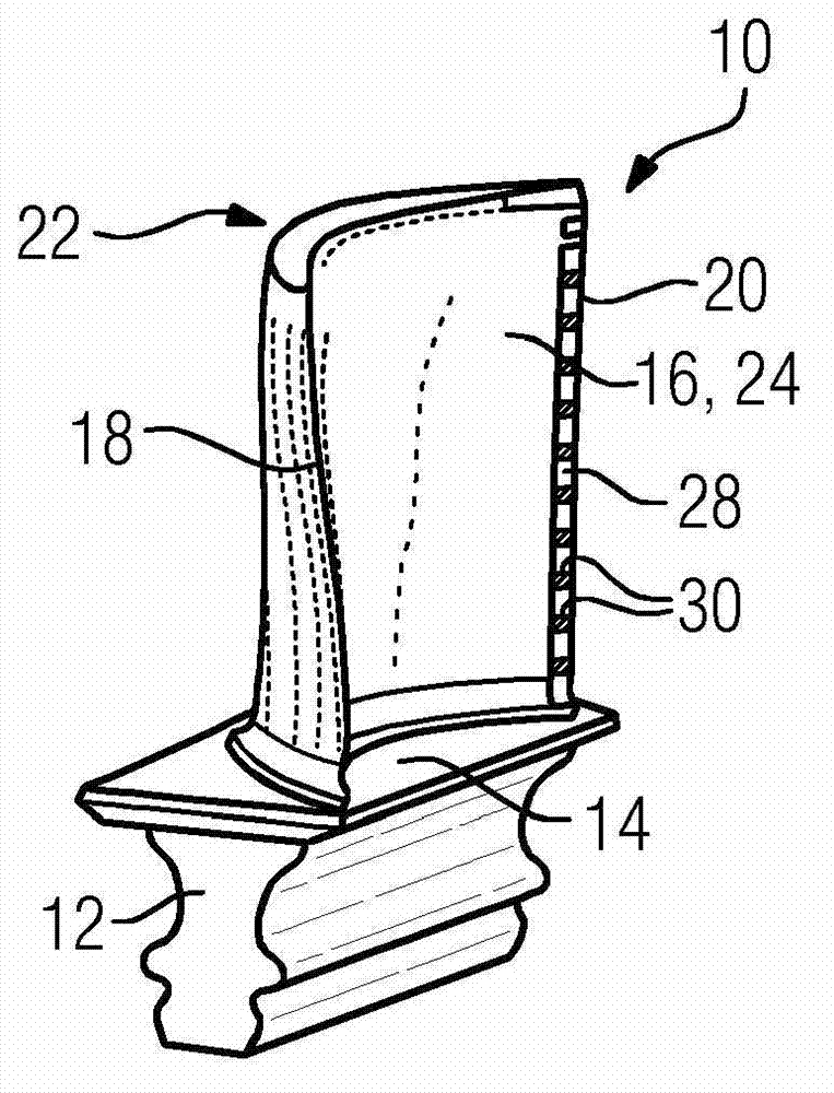
[0030] exist figure 1 A perspective view of a gas turbine blade 10 according to the present invention is shown in . Gas Turbine Blades 10 According to figure 1 are formed as rotor blades. The invention can also be used in guide vanes (not shown) of gas turbines. The turbine blade 10 comprises a fir-tree-shaped blade root 12 in cross-section and a platform 14 arranged thereon. Attached to the platform 14 is a streamlined curved airfoil 16 having a leading edge 18 and a trailing edge 20 . Cooling openings arranged as so-called “spoutheads” are provided on the leading edge 18 , out of which cooling medium flowing inside, preferably cooling air, can flow out. Leaf Body 16 Includes - About figure 1- The suction side wall 22 on the rear side and the pressure side wall 24 on the front side. A plurality of openings 28 are provided along the rear edge 20 , which are separated from o...


PUM


Abstract

The turbine blade (10) has a leaf blade (16) through which a hot gas is flowable. A throttle element is equipped with two projections at respective openings (28) with respect to a flow direction of a channel. Each projection is attached to one of two surfaces (34,36) arranged in an inner-facing manner.

Description

technical field [0001] The invention relates to a turbine blade with an airfoil around which hot gas can flow, said airfoil comprising a suction side wall and a pressure side wall, said suction side wall and said pressure side wall extending from The common leading edge extends to the trailing edge, wherein at least one opening is provided on the trailing edge for the discharge of the cooling medium that previously cooled the blade airfoil, said at least one opening being in fluid connection with a cavity provided in the blade airfoil by means of a channel, The channel is also delimited by the inwardly facing surface of the suction side wall and the inwardly facing surface of the pressure side wall, and a throttling element is provided for regulating the quantity of cooling medium flowing out of the opening. Background technique [0002] A turbine blade of the type mentioned at the outset and a casting core for producing such a turbine blade are known, for example, from WO 2...

Claims


Application Information

Patent Timeline
Patent Type & Authority Applications(China)
IPC IPC(8): F01D5/18
CPCF05D2260/2212F05B2260/202F05B2260/2241F05D2260/22141F05D2250/60F01D5/187F05D2240/122F05D2240/304F01D25/12F05D2260/202F05D2250/184F05B2260/222
Inventor 法蒂·艾哈迈德
Owner SIEMENS AG
Why Eureka
Try Eureka