
Optical diffraction element and endoscope

A diffractive optical element and endoscope technology, which is applied in the field of diffractive optical elements and endoscopes, can solve the problems of high cost, insufficient mass production, and easy warping

Inactive Publication Date: 2013-05-01
OLYMPUS CORP
View PDF13 Cites 1 Cited by
  • Summary
  • Abstract
  • Description
  • Claims
  • Application Information

AI Technical Summary

Problems solved by technology

As a result, high diffraction efficiency of the first-order diffracted light (hereinafter, simply referred to as "diffraction efficiency") can be realized in a wide wavelength region, but since one of the two-layer optical elements is made of glass material, There are disadvantages such as difficult processing of relief patterns, insufficient mass productivity, and high cost
[0012] In addition, since the diffractive optical elements of Patent Documents 4 to 7 are made of resin, they are excellent in processability and mass productivity, and can be manufactured at low cost. However, the condition of the center thickness is not suitable, and warping and peeling tend to occur during the manufacturing process. such a bad situation

Method used


Image

  • Optical diffraction element and endoscope
  • Optical diffraction element and endoscope
  • Optical diffraction element and endoscope

Examples


Embodiment Construction

[0088] Hereinafter, a diffractive optical element according to an embodiment of the present invention will be described with reference to the drawings.

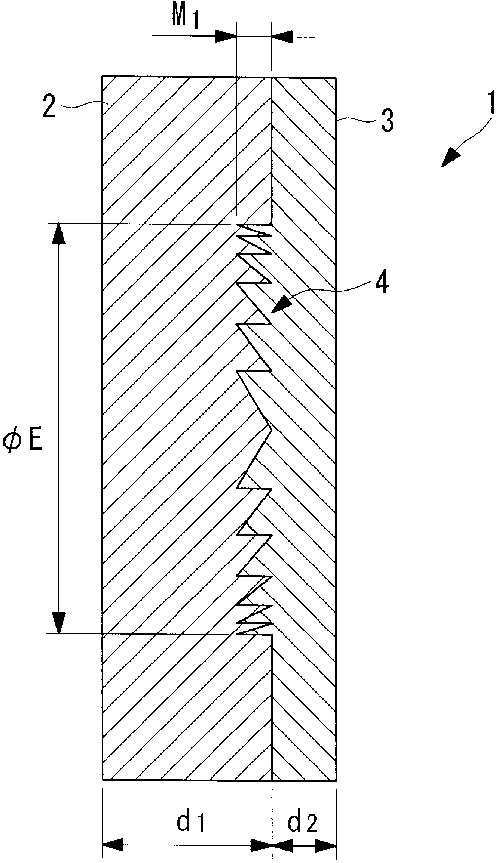
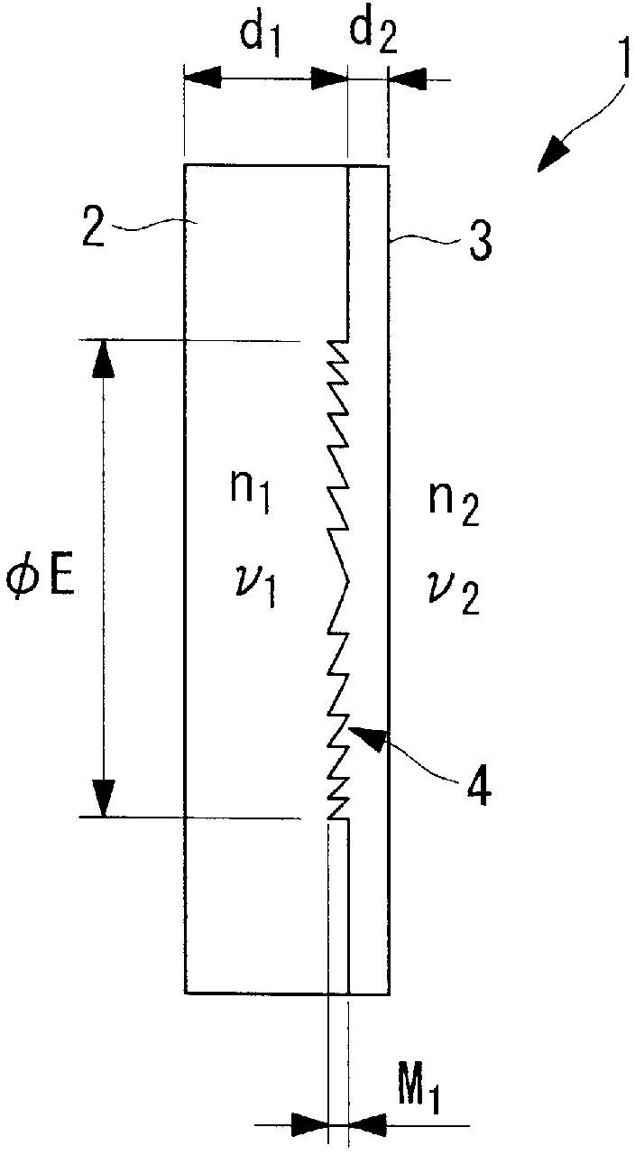
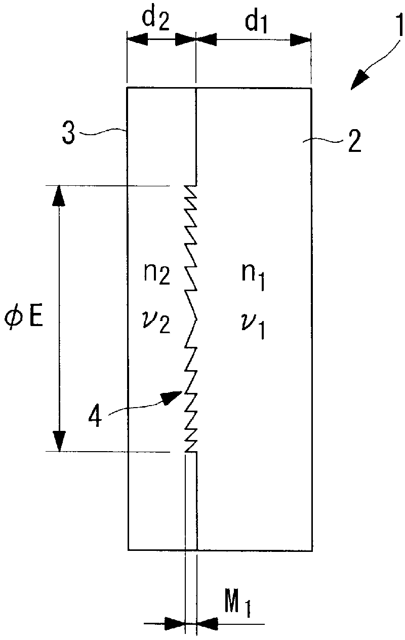
[0089] like figure 1 As shown, the diffractive optical element 1 of this embodiment is a multilayer diffractive optical element 1 in which the first optical material layer 2 and the second optical material layer 3 are laminated.

[0090] The two optical material layers 2, 3 are respectively composed of different energy curable resins.

[0091] The first optical material layer 2 is the first cured optical material layer, with a central thickness of d 1 , the refractive index in the d-line is n 1 , the Abbe number is ν 1 . The second optical material layer 3 is a post-cured optical material layer with a central thickness of d 2 , the refractive index in the d-line is n 2 , the Abbe number is ν 2 .

[0092] In addition, a relief pattern 4 is formed on the interface between the first optical material layer 2 and the secon...


PUM


Abstract

Provided is an optical diffraction element (1) in which two optical material layers (2, 3) comprising cured resin having different energies are laminated, and a relief pattern (4) is formed at the interface of the two optical material layers (2, 3), the optical diffraction element (1) satisfying the following conditional expressions: 0.01<d2 / d1<0.2 (1); 0.05<d1 / [phi]E<1.0 (2); 0.0005<d2 / [phi]E<0.1 (3); d1 is the central thickness (mm) of the one optical material layer (2) that is cured first, d2 is the central thickness (mm) of the other optical material layer (3) that is subsequently cured, and [phi]E is the effective diameter (mm) of the relief pattern (4).

Description

technical field [0001] The present invention relates to a diffractive optical element and an endoscope. Background technique [0002] Conventionally, as a diffractive optical element, since it has the characteristic of being able to correct the chromatic aberration of the optical system favorably, it has been disclosed in the following documents (for example, refer to Patent Documents 1 to 7). [0003] Patent Document 1: Japanese Patent Application Laid-Open No. 2-179605 [0004] Patent Document 2: Japanese Patent Application Laid-Open No. 11-271513 [0005] Patent Document 3: Japanese Patent Application Laid-Open No. 11-287904 [0006] Patent Document 4: Japanese Unexamined Patent Publication No. 2007-273012 [0007] Patent Document 5: Japanese Patent Laid-Open No. 2009-197217 [0008] Patent Document 6: Japanese Unexamined Patent Publication No. 2005-107298 [0009] Patent Document 7: International Publication No. 2007 / 111077 [0010] However, the diffractive optical...

Claims


Application Information

Patent Timeline
Patent Type & Authority Applications(China)
IPC IPC(8): G02B5/18A61B1/00G02B5/32G02B23/24
CPCG02B27/4205G02B23/2407A61B1/00096A61B1/00163A61B1/0011G02B27/0018G02B27/0037
Inventor 片仓正弘
Owner OLYMPUS CORP
Learn More