Continuous type infrared corncob drying machine

A corn cob and drying machine technology, which is applied in the fields of drying and preserving seeds, food processing, etc., can solve the problems of slow heat transfer, long drying time, and inconvenient packaging, etc., and achieve reduced hindrance and fast drying speed , Improve the effect of uniformity

Inactive Publication Date: 2013-05-08
SHANDONG UNIV OF TECH
View PDF9 Cites 18 Cited by
  • Summary
  • Abstract
  • Description
  • Claims
  • Application Information

AI Technical Summary

Problems solved by technology

The corn ear drying equipment involved in the above-mentioned patent can already dry wet corn ears normally, but the temperature of the corn ears flowing out from the discharge port after drying is too high, which is not convenient for packaging and wastes energy; After the moisture content reaches the requirement, make it heat exchange with normal temperature air in the lower channel of the conveying device, and then apply for a national invention patent, the application number is: 201310052038.9
However, the cob dryers involved in the above-mentioned patents all adopt hot air convection drying, and the temperature of the hot air is generally relatively high, and the drying is carried out under normal pressure, so sometimes the corn kernels will burst; if the temperature of the hot air is lowered, the heat transfer rate will decrease. slow, longer drying time
In addition, the energy consumption of hot air drying is relatively high

Method used


Image

  • Continuous type infrared corncob drying machine
  • Continuous type infrared corncob drying machine
  • Continuous type infrared corncob drying machine

Examples


Embodiment Construction

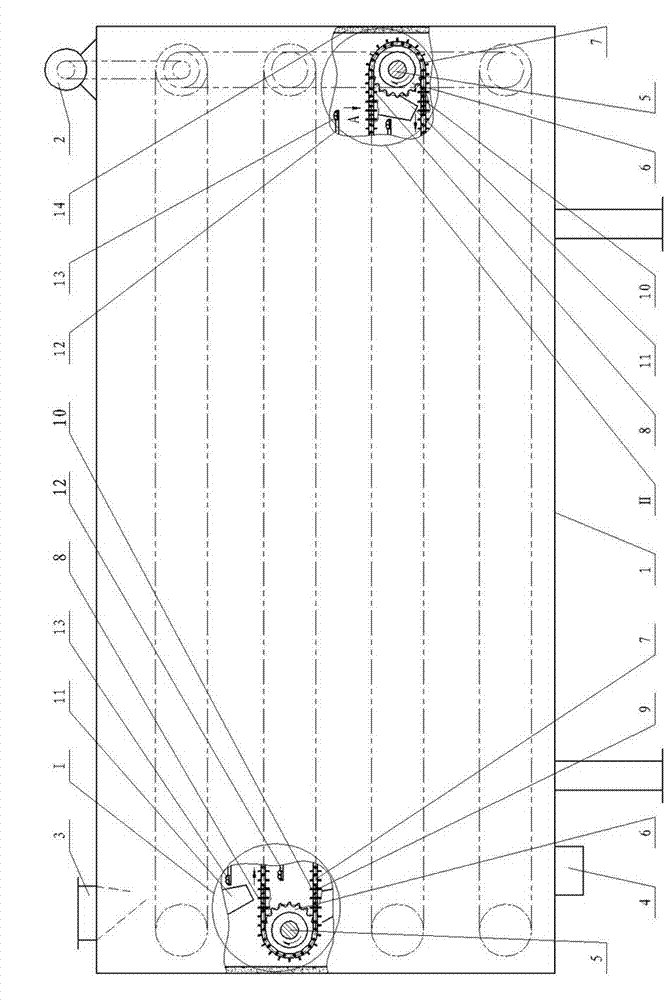
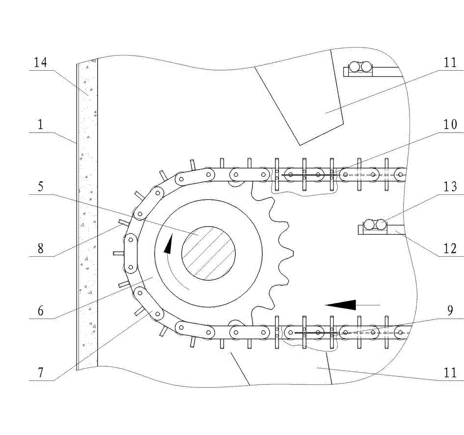
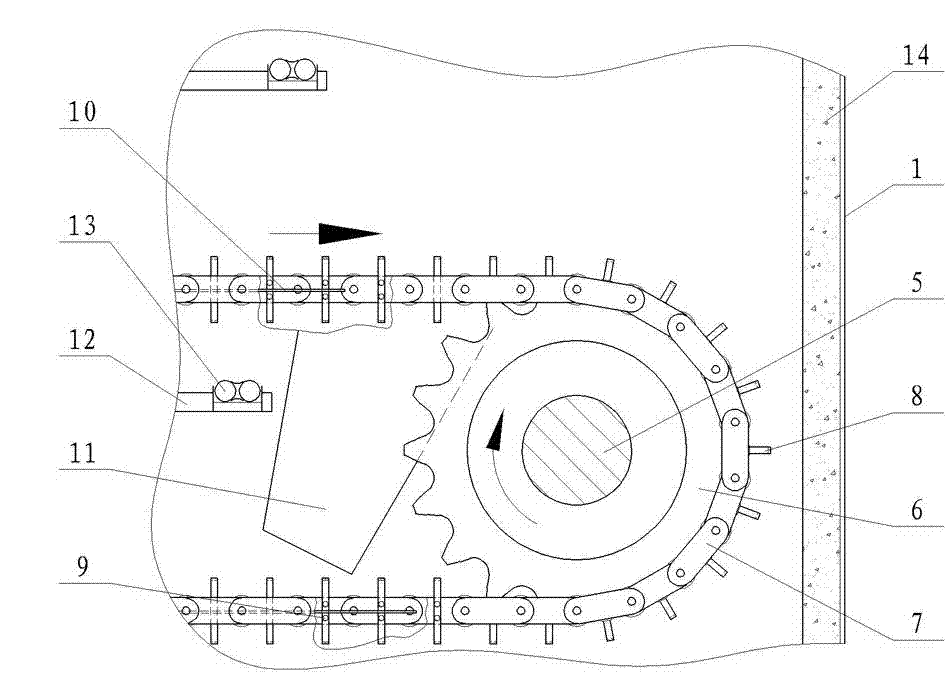
[0019] 1. Box body 2, transmission device 3, material inlet 4, material outlet 5, shaft 6, sprocket 7, chain 8, material lever 9, screw 10, support plate 11, material guide trough 12, radiation frame 13. Infrared radiation element 14. Thermal insulation layer.

[0020] exist Figure 1~5 In the shown embodiment: the top left end of the rectangular box body 1 is provided with a material inlet 3 , and the same end is provided with a material outlet 4 at the bottom of the box body 1 . There are four conveying devices along the length direction in the box body 1, and two shafts 5 of the same conveying device are arranged horizontally at both ends of the box body 1 along the length direction, and both ends of the two shafts 5 are supported on the vertical wall of the box body 1 , and the axis of the shaft 5 is perpendicular to the length direction of the box body 1; the transmission device 2 installed on the top of the box body 1 away from the right end of the feed port 3 passes th...


PUM


Abstract

The invention provides a continuous type infrared corncob drying machine which is characterized in that a box body is internally provided with a plurality of conveying devices driven by a transmission device to run, wherein I type and II type material pulling rods with two different lengths are fixedly arranged between two chains of the same conveying device at an interval; parts of each conveying device, which correspond to upper and lower sections of horizontal sections of the chains, are respectively provided with material supporting plates; material guide grooves are arranged below the tail ends of the material supporting plates; radiation devices are arranged above the material supporting plates; radiation racks of the radiation devices are suspended on the box body; the two ends of an infrared radiation element which downwards radiates infrared rays in a single direction are mounted on the radiation racks; and a feeding opening is arranged on the top of the box body, and a discharging opening is formed at the bottom of the box body. The continuous type infrared corncob drying machine disclosed by the invention has the advantages of high heat transferring efficiency, low energy consumption and good drying uniformity.

Description

technical field [0001] The invention provides a continuous infrared corn cob dryer, which is mainly used for dehydrating and drying wet corn cobs with high moisture content just after picking from corn stalks. Background technique [0002] China is a large agricultural country, especially in Shandong, Henan and Northeast China, which are the major food producing areas such as corn. With the development of the breeding industry and the increase in the demand for feed, the planting area of ​​corn has gradually expanded, and the output has increased year by year. The harvest moisture of corn is generally 25%-35%. If there is no good corn drying equipment, it will cause a lot of loss due to excessive moisture and mold. Therefore, farmers' demand for corn dryers is becoming more and more urgent. It is of great significance to develop corn dryers with high precipitation, good drying uniformity and high quality to promote the development of corn industry. [0003] At present, the...

Claims


Application Information

Patent Timeline
Patent Type & Authority Applications(China)
IPC IPC(8): A23B9/08
CPCY02P60/85
Inventor 王相友孙传祝
Owner SHANDONG UNIV OF TECH
Why Eureka
Try Eureka