Dental syringe

A syringe, dental technology, used in dentistry, dental drilling, medical science, etc., can solve problems such as temperature control is not very accurate, handpiece and fluid overheating, etc.

Active Publication Date: 2013-05-08
M O COM
View PDF3 Cites 3 Cited by
  • Summary
  • Abstract
  • Description
  • Claims
  • Application Information

AI Technical Summary

Problems solved by technology

PTCs are self-adjusting resistors, but their temperature control is not very precise and can cause overheatin

Method used


Image

  • Dental syringe
  • Dental syringe
  • Dental syringe

Examples


Embodiment Construction

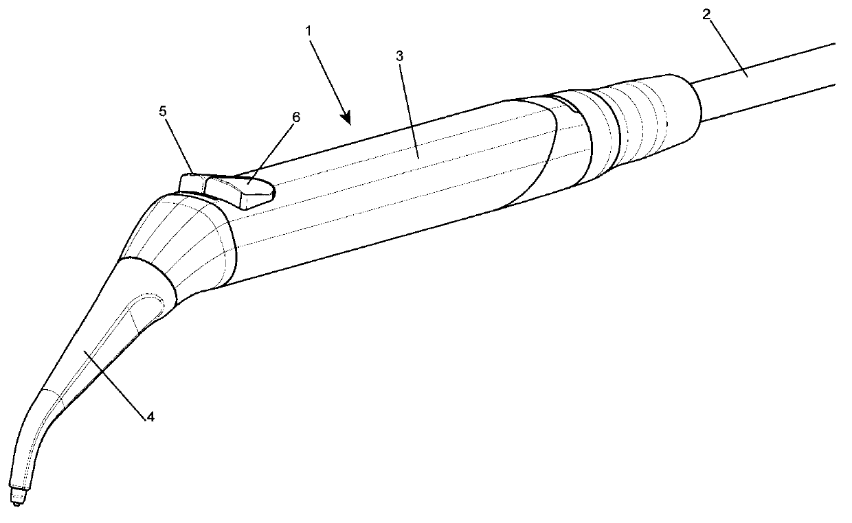
[0022] figure 1 A dental syringe is generally shown. Reference numeral 2 denotes a cable connecting the syringe to a dental unit (not shown), 3 denotes a syringe housing, 4 denotes a nozzle, 5 denotes an air supply button, and 6 denotes a water supply button. Simultaneously press buttons 5 and 6 to supply spray.

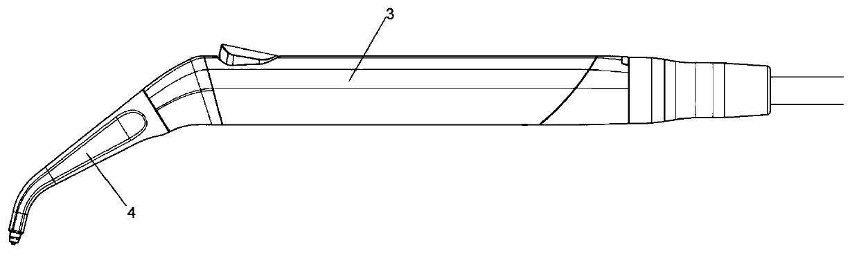
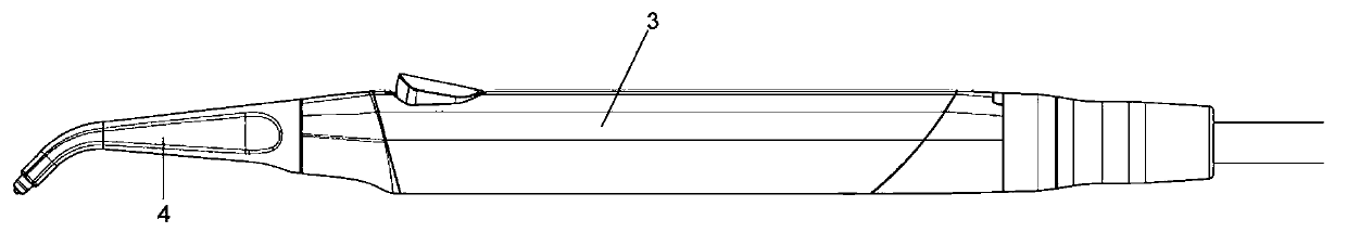
[0023] Figure 2A shown in different stereograms figure 1 syringe. Figure 2B A different embodiment is shown in which the nozzle 4 does not have an L shape but coincides with the axis of the syringe body 3 (pen-shaped syringe).

[0024] image 3 Shown is the inner body 7 of the syringe, which is sterilized once the housing 3 has been removed. From a comparison with Fig. 2, one can understand the fact that the housing 3 partly covers the body 7 of the syringe when mounted. In this figure, 8 is the part where the valves are located; these valves supply air and water when they are actuated by buttons 5 and 6 . Part 9 includes the object of the invention - the f...


PUM


Abstract

Dental syringe (1) comprising: a supply cord (2) connecting it to a dental unit, a housing (3), a nozzle (4), a couple of valves supplying and stopping water and air, and heating elements (20, 26) for the supplied fluids, switchable on by a ring nut (10), wherein the heating systems are contained inside housing (3) and comprising means (21, 22, 27, 28, 29) for fluids temperature control, capable of keeping said fluids warm even when syringe (1) is at rest, and in that the water heating system comprises a heat exchanger (13) and at least a heating element (20), a temperature sensor (21) at the heat exchanger, a temperature sensor (22) at the exit from the heat exchanger (13), and a microprocessor (29).

Description

technical field [0001] The present invention relates to dental syringes, ie devices optionally supplied with water, air or a spray comprising both said fluids, and in particular to devices for heating said fluids. Background technique [0002] Such syringes are well known in the art, wherein such syringes are used to blow air / dry the treatment site, or to clean the treatment site with a jet of water or a spray comprising water and air. The fluid supplied may be warmed (approximately body temperature, 37°C) in order to avoid triggering pain or defense responses. On the other hand, in some therapeutic situations it may be necessary to use fluids at room temperature, for example to test the patient's reflexes or to limit blood loss. [0003] In the known art there are several examples of heating devices for dental syringes. Such devices can be grouped into two different categories: obsolete devices, where the fluid heating means is upstream of the injector (in the dental unit...

Claims


Application Information

Patent Timeline
IPC IPC(8): A61C17/02
CPCA61C17/0202A61C1/0069A61C17/022A61C17/0217
Inventor V·博萨里M·扎内蒂
Owner M O COM
Why Eureka
Try Eureka