
Electric gravity reduction training frame
A kind of training frame and electric technology, which is applied in the direction of equipment to help people walk, physical therapy, etc., can solve the problems of not being able to adapt to the requirements of the patient's weight reduction force, the height of the weight reduction force cannot be adjusted, and the size of the weight reduction force cannot be accurately set.
- Summary
- Abstract
- Description
- Claims
- Application Information
AI Technical Summary
Problems solved by technology
Method used
Image

Examples
Embodiment Construction
[0027] The present invention will be further described below in conjunction with the accompanying drawings.
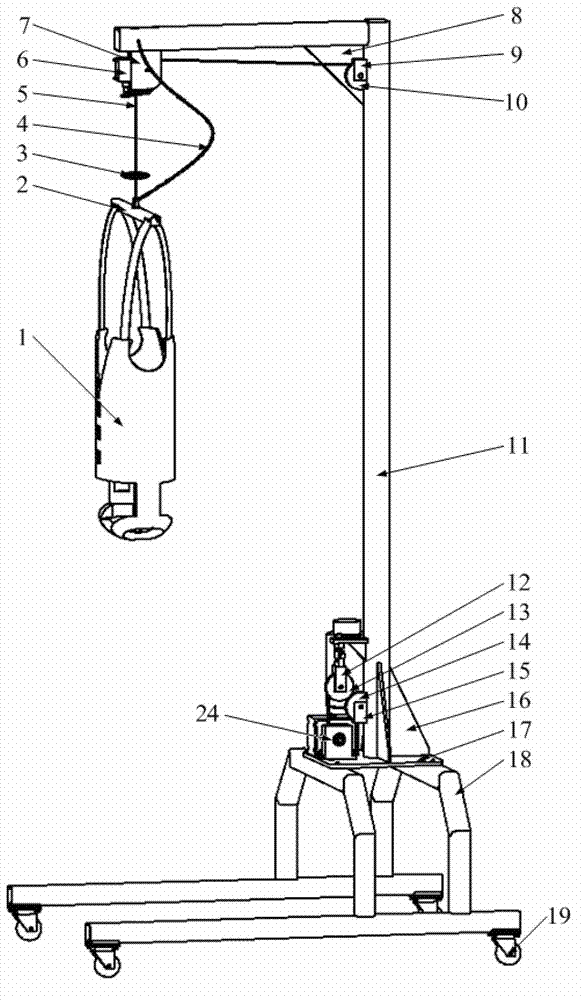
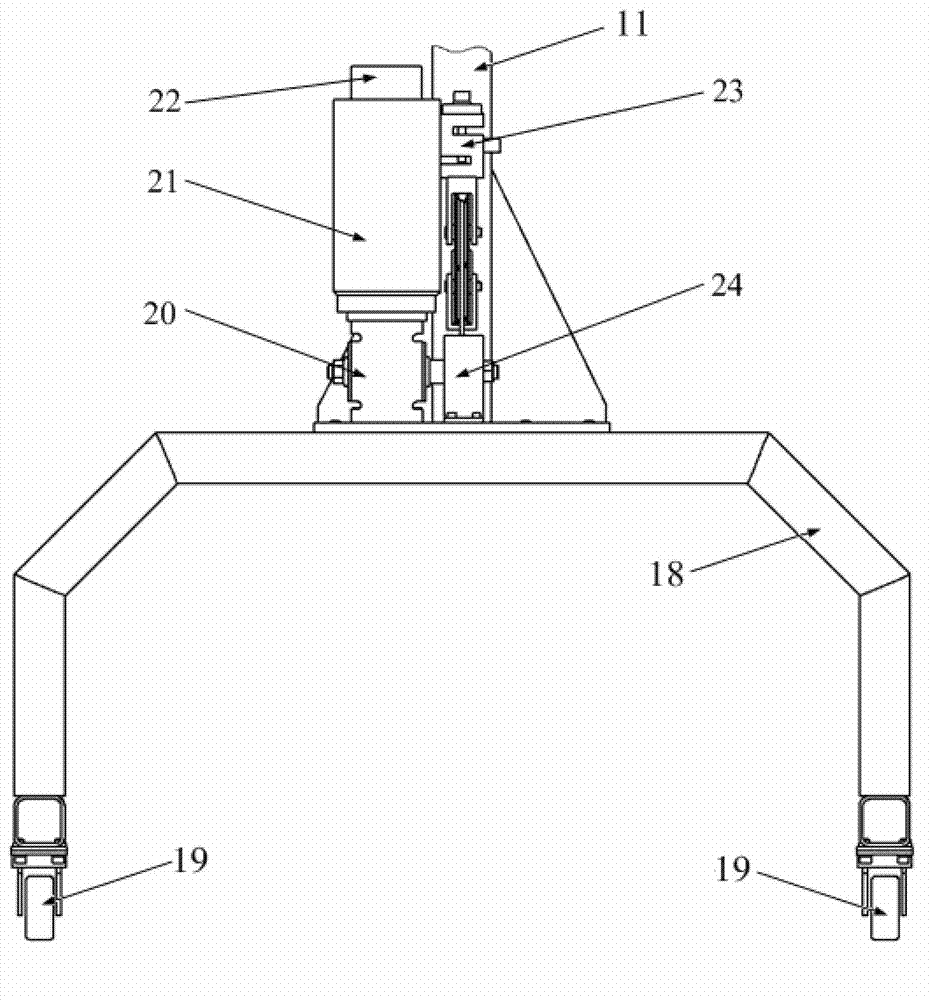
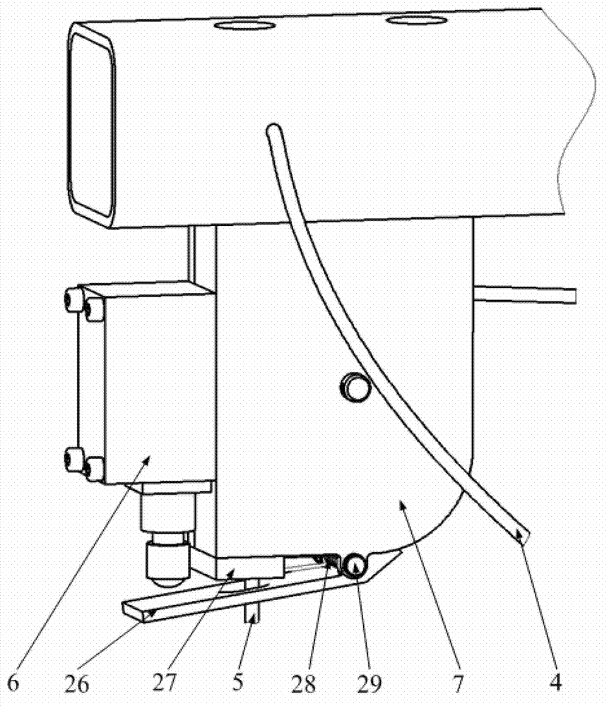
[0028] like Figure 1 to Figure 5 Shown is an electric weight loss training frame, including a controller, a base support mechanism, a drive mechanism, a weight reduction force adjustment mechanism, a pulley assembly, a limit protection mechanism and a suspension vest 1 .
[0029] Described base support mechanism comprises base frame 18, base plate 17 and inverted L-shaped vertical support 11, and described vertical support 11 comprises horizontal square tube and cubic tube, and the rear end of the top of described cubic tube and horizontal tube is fixed, and cubic The lower end of the pipe is fixed on the base plate 17; casters 19 are arranged below the base frame 18, and the casters 19 have a brake structure; the base plate 17 is fixed on the base frame 18. The A rib 8 and the B rib 31 are used to strengthen the fixation between the horizontal tube and the cubic tub...
PUM
 Abstract
Description
Claims
Application Information