Combination frame module, component frame module and tool set structure and installing and dismantling method thereof
A combination frame and component technology, which is applied in the fields of formwork/formwork components, formwork/formwork/work frame, and on-site preparation of building components, can solve the problems of high-altitude operation, high construction risk, and long construction period.
- Summary
- Abstract
- Description
- Claims
- Application Information
AI Technical Summary
Problems solved by technology
Method used
Image

Examples
Embodiment Construction
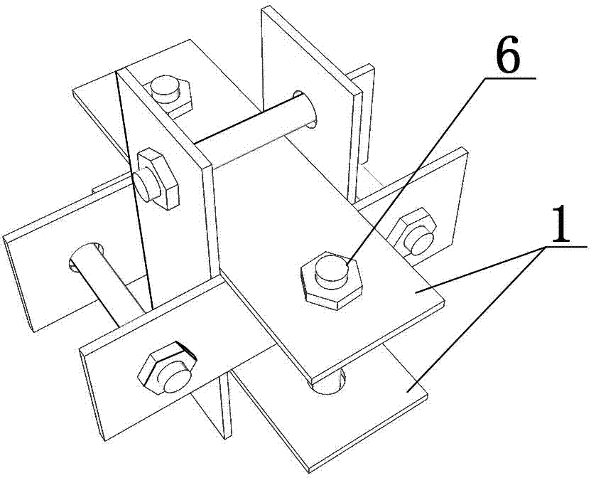
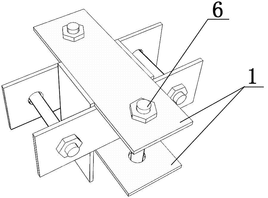
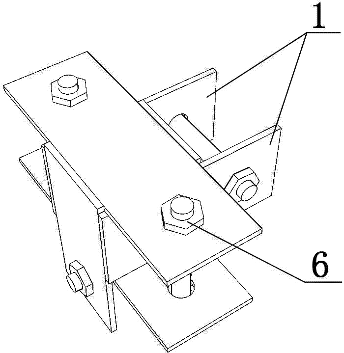
[0169] Examples see Figure 1-34 As shown in this combination frame mold, the combination frame mold is composed of a mold frame and a template combination.
[0170] The mold frame is a rectangular mold frame composed of one mold frame element, or a grid mold frame formed by splicing two or more mold frame elements.
[0171] The mold frame elements are rectangular mold frame elements formed of four frame parts facing each other in parallel and connected with each other by splint joints, and more than two mold frame elements are connected with each other by splint joints.
[0172] The mold frame element includes standard series, among which:
[0173] Standard width series include 600mm, 750mm, 900mm, 1200mm, 1500mm, 1800mm.
[0174] Standard length series include: 1200mm, 1800mm, 2400mm, 2700mm, 3000mm, 3300mm, 3600mm.
[0175] When the length of the frame is greater than or equal to 1200mm, the frame is a steel standard length frame; the standard length frame includes 900mm...
PUM
 Abstract
Description
Claims
Application Information