Well head device with combined sealing, double-tube gas injection and remote control

A remote control, combined sealing technology, used in sealing/isolation, wellbore/well components, earth-moving drilling, etc. Adapt to the problems of long-distance control of oil and gas wells, and achieve the effect of light weight, compact structure and good sealing performance

Inactive Publication Date: 2013-05-08
JIANGSU HONGTAI PETROCHEM MACHINERY
View PDF10 Cites 6 Cited by
  • Summary
  • Abstract
  • Description
  • Claims
  • Application Information

AI Technical Summary

Problems solved by technology

Existing ordinary wellhead devices usually add a single hanger and tubing to the tubing spool, a simple rubber sealing structure, and simple manual on-site control, which cannot meet the production requirements of water injection, gas injection or layered gas injection. It cannot adapt to the working environment of strong corrosion of carbon dioxide gas, and cannot adapt to the requirements of remote control of oil and gas wells
Existing individual new products such as "coaxial double-layer gas injection wellhead device" (Chinese Patent Publication No.: CN102242614A) just superimpose two traditional oil pipe heads, adopt simple rubber sealing structure and manual on-site control method, only It solves the problem of layered gas injection, but cannot achieve the functions and effects that satisfy oil and gas field users

Method used


Image

  • Well head device with combined sealing, double-tube gas injection and remote control
  • Well head device with combined sealing, double-tube gas injection and remote control
  • Well head device with combined sealing, double-tube gas injection and remote control

Examples


Embodiment Construction

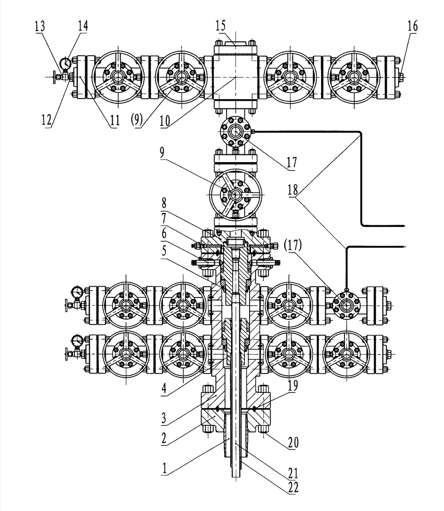
[0011] The specific embodiment of the present invention will be further described below in conjunction with accompanying drawing:

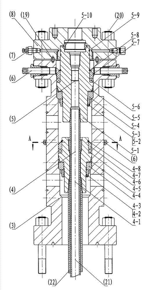
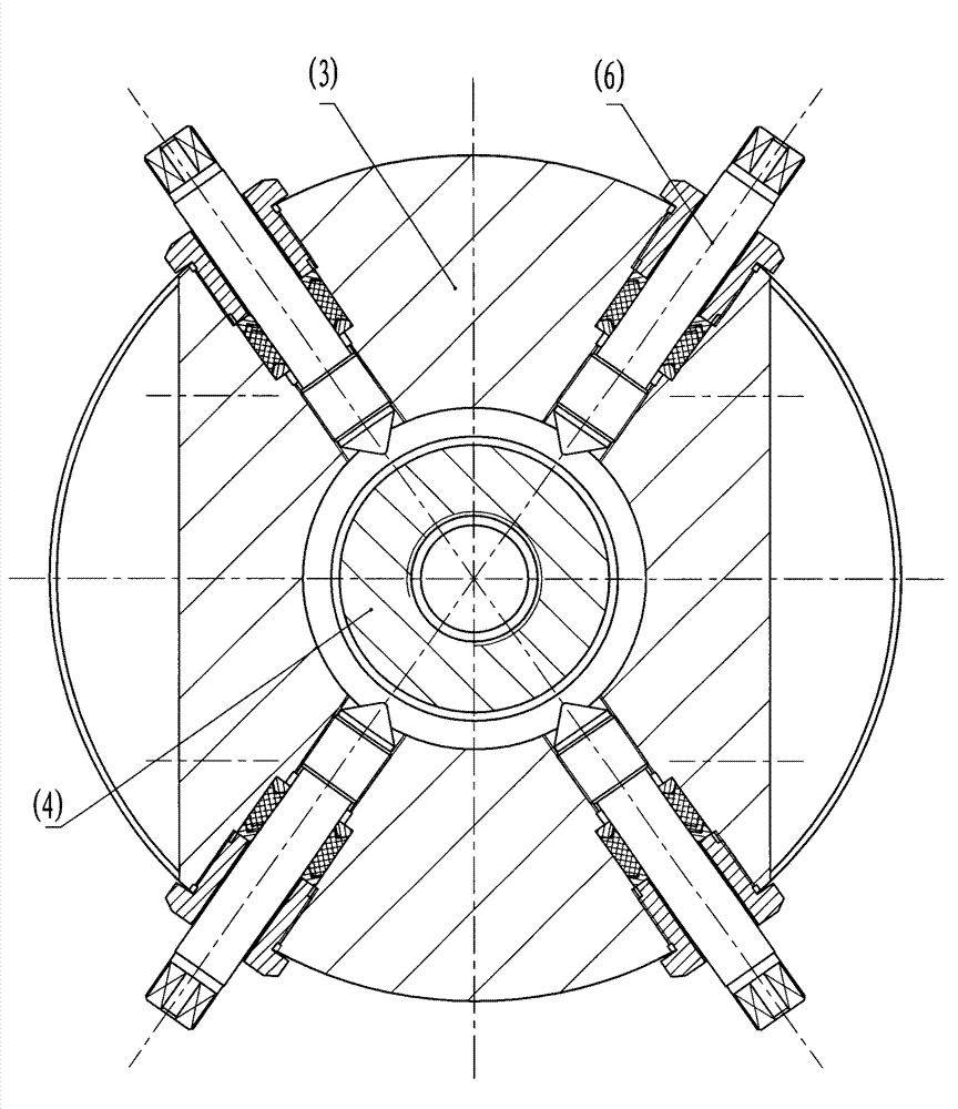
[0012] figure 1 Among them, the present invention is composed of casing connectors, tubing heads, Christmas trees, gas injection pipe valves, measurement and control pipe valves, seals, and connectors. Casing connectors mainly include casing nipples (1) and casing flanges (2); tubing heads mainly include tubing head shells (3), lower hanger parts (4), upper hanger parts (5) and Jacking screw part (6); Christmas tree mainly includes grease injection valve (7), tubing reducing joint (8), flat valve (9), cross (10), threaded flange (11), inner joint (12) , stop valve (13), pressure gauge (14), blind hole cover plate (15), pipe plug (16) and hydraulic control valve (17). There are two rows of gas injection pipe valve parts connected to one side of the oil pipe head, mainly including two flat valves (9) or one flat valve (9) plus a hydraulic control ...


PUM


Abstract

The invention discloses a well head device with combined sealing, double-tube gas injection and remote control and relates to petroleum machinery and well head devices. The well head device with the combined sealing, the double-tube gas injection and the remote control is characterized in that an tubing head shell is an integral six-link part, an upper hanger component and a lower hanger component are installed in an upper channel and a lower channel, and the upper hanger component and the lower hanger component are both provided with sealing structures that metal sealing rings are combined with rubber sealing rings. In four channel openings on flat surfaces of two side walls of the tubing head shell, by sealing backing rings, bolts and nuts, two gas injection tube valves parallel top and bottom and two measure and control tube valves parallel top and bottom are respectively connected in a linkage mode. The gas injection tube valves and the measure and control tube valves on two sides are all provided with dual-valve structures, and the upper channel and the lower channel of a Christmas tree are both provided with dual-valve structures. On the outer sides of an upper row of flat valves of the gas injection tube valve fixed on the flat surface of one side of the tubing head shell and on a channel below a cross of the Christmas tree, hydraulic control valves are respectively connected in series. The structure is compact, sealing is good, installation is convenient, and the well head device is safe and reliable, and can conveniently carry out the remote control, layering gas injection and oil gas extraction.

Description

technical field [0001] The invention relates to petroleum machinery and wellhead devices in gas injection production equipment in oil and gas fields. Background technique [0002] It is an increasingly popular oil and gas extraction technology to extract oil and natural gas by water injection or carbon dioxide gas injection, or by layered gas injection. Existing ordinary wellhead devices usually add a single hanger and tubing to the tubing spool, a simple rubber sealing structure, and simple manual on-site control, which cannot meet the production requirements of water injection, gas injection or layered gas injection. It cannot adapt to the working environment of strong corrosion of carbon dioxide gas, and cannot adapt to the requirements of remote control of oil and gas wells. Existing individual new products such as "coaxial double-layer gas injection wellhead device" (Chinese Patent Publication No.: CN102242614A) just superimpose two traditional oil pipe heads, adopt si...

Claims


Application Information

Patent Timeline
Patent Type & Authority Applications(China)
IPC IPC(8): E21B33/03
Inventor 姜玉虎朱宏武李亚洲丁中铭姜金维张学清顾邦良李海荣周世海
Owner JIANGSU HONGTAI PETROCHEM MACHINERY
Why Eureka
Try Eureka