Bidirectional pounding and cutting excavating method and bidirectional pounding and cutting excavator for implementing same

A technology of fuselage and guide parts, applied in the field of machinery, can solve the problems of increasing power consumption, consuming a lot of manpower, material resources and time, and reducing service life

Active Publication Date: 2013-05-08
刘素华
View PDF5 Cites 29 Cited by
  • Summary
  • Abstract
  • Description
  • Claims
  • Application Information

AI Technical Summary

Problems solved by technology

[0007] Based on the above requirements, there have been many ways to use lump minerals. For example, a high-efficiency block coal shovel is arranged in one direction of the coal mining head, and the fuselage must be turned when reverse coal mining. However, due to the small underground space, the general The mining roadway is less than 6 meters wide, and the length of t

Method used


Image

  • Bidirectional pounding and cutting excavating method and bidirectional pounding and cutting excavator for implementing same
  • Bidirectional pounding and cutting excavating method and bidirectional pounding and cutting excavator for implementing same
  • Bidirectional pounding and cutting excavating method and bidirectional pounding and cutting excavator for implementing same

Examples


Embodiment 1

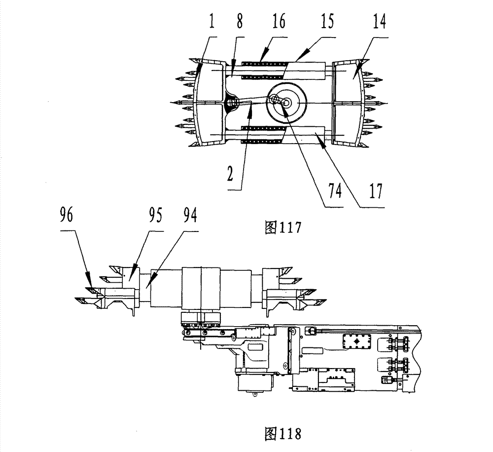
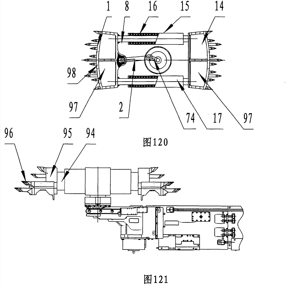
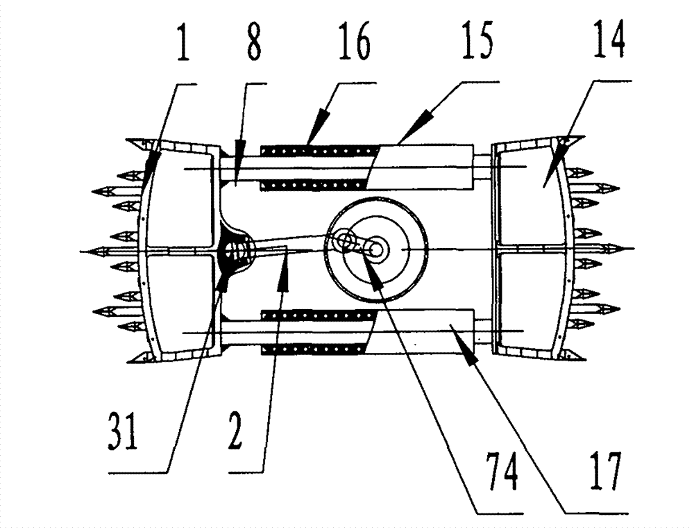
[0634] Figure 1 to Figure 3 It is the two-way punching mining machine described in Embodiment 1. The two-way punching mining machine includes a fuselage 6, a walking part 5, a lifting part 4, a reciprocating impact part 3, etc., and the reciprocating impact part 3 includes an impact guide 8, etc. Both ends of the impact guide 8 are provided with an impact head 1, etc., the reciprocating impact part 3 also includes an impact drive device 7, etc., the impact drive device 7 includes a crank impact drive device 17, etc., and the crank impact drive device 17 includes a power impact member 2, etc. The power impact part 2 drives the impact guide part 8 to reciprocate, and the impact guide part 8 drives the impact head 1 to impact the coal seam mining material. The power impact part 2 and the impact guide part 8 are separated or integrated, and the reciprocating impact part 3 is arranged in the lifting part 4, the lifting part 4 is arranged on the fuselage 6, and the running part 5 i...

Embodiment 2

[0642] Figure 4 It is the two-way punching mining machine described in Embodiment 2. The two-way punching mining machine includes a reciprocating impact part 3 , and the reciprocating impact part 3 also includes an impact driving device 7 , etc., and the impact driving device 7 includes a hydraulic impact driving device 10 . The hydraulic impact driving device 10 includes a hydraulic cavity 11, a piston 12, a hydraulic impact rod 13 and the like.

[0643] The impact driving device 7 can also be a pneumatic impact driving device 54 .

Embodiment 3

[0645] Figure 4 It is the two-way punching mining machine described in Embodiment 2. The two-way punching mining machine includes a running part 5. The running part 5 drives the fuselage 6 to move forward and backward, and the power impact part 2 drives the impact guide part 8 to reciprocate. The impact guide 8 drives the impact head 1 to impact the coal wall or rock wall, so as to complete the forward and backward mining and falling of materials without turning the machine body. The power impact member 2 and the impact guide 8 are separated or integrated.

[0646] The dynamic impact member 2 and the impact guide member 8 can also be of separate structure.

[0647] According to the above structure, the present invention also includes a method for two-way punching and mining, which is realized by the following steps:

[0648] The first step: the walking part 5 drives the fuselage 6 to move forward, the power impact member 2 drives the impact guide 8 to reciprocate, and the im...


PUM


Abstract

The method provided by the invention comprises the following steps: a machine body, a walking part, a lifting part, a reciprocating pounding part and the like are arranged; a pounding guide element and the like are arranged on a pounding guide device; pounding heads are arranged at two ends of the pounding guide element, so that a power pounding element drives the pounding guide element; the reciprocating pounding part is arranged on the lifting part; the lifting part is arranged on the machine body; and the walking part drives the machine body to move ahead and retreats so as not to turn the machine body to excavate and drop materials forward and backward. Equipment provided by the invention comprises the machine body, the walking part, the lifting part, the reciprocating pounding part and the like; the reciprocating pounding part comprises the pounding guide device, the pounding driving device and the like; the pounding heads are both arranged at two ends of the pounding guide element; the pounding driving device comprises the power pounding element and the like; the power pounding element drives the pounding guide element to move in a reciprocating mode; the pounding guide element drives the pounding heads to pound; the reciprocating pounding part is arranged on the lifting part; the lifting part is arranged on the machine body; the walking part drives the machine body to move ahead and retreat so as not to turn the machine body to excavate and drop materials forward and backward.

Description

technical field [0001] The invention belongs to the field of machinery, in particular to a method for two-way punching and mining applicable to the field of mining and a two-way punching mining machine for implementing the method. Background technique [0002] The currently widely used mining equipment is drum shearer and drill-washing roadheader, whose working principle is milling blanking, which determines that the crushing of this mining method is relatively large, especially in the state of compressive stress. A large amount of energy reduces the production efficiency and block rate. The crushing process also produces a large amount of dust, which causes problems such as bad mining environment and potential safety hazards, and greatly reduces the economic value and use value of the excavated materials. [0003] With the development of mining technology, a new mining equipment is urgently needed because: [0004] (1) Lump coal is a necessity for the development of the na...

Claims


Application Information

Patent Timeline
IPC IPC(8): E21C27/00E21C35/08E21C31/02
Inventor 刘素华
Owner 刘素华
Why Eureka
Try Eureka