
Oil separating device of compressor

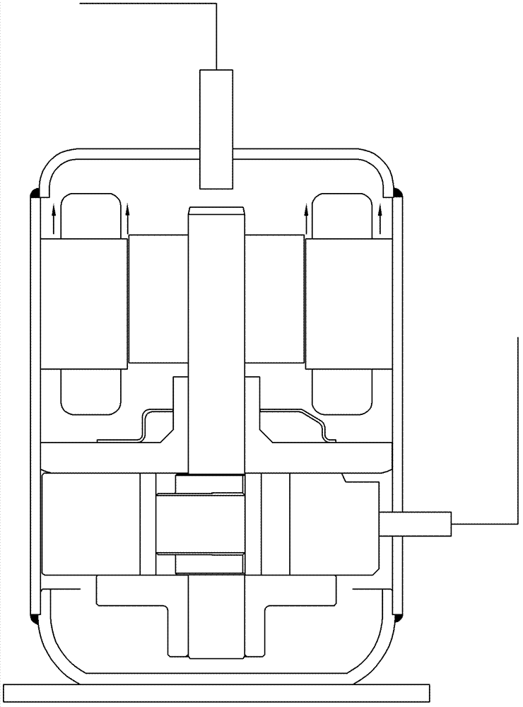
A technology of oil separation and compressor, which is applied in the direction of mechanical equipment, machine/engine, liquid variable capacity machinery, etc., to achieve the effects of improving stability, improving heat exchange efficiency, and improving gas circulation

Active Publication Date: 2013-05-08
GUANGDONG MEIZHI COMPRESSOR
View PDF5 Cites 2 Cited by
  • Summary
  • Abstract
  • Description
  • Claims
  • Application Information

AI Technical Summary

Problems solved by technology

[0003] The purpose of the present invention is to provide an oil separation device for improving the gas circulation in the compressor, reducing the oil discharge of the compressor, reducing the adverse effect of lubricating oil on the heat exchange efficiency of the air conditioning system, and improving the stability of the compressor at the same time. To overcome the deficiencies in the prior art

Method used


Image

  • Oil separating device of compressor
  • Oil separating device of compressor
  • Oil separating device of compressor

Examples


Embodiment Construction

[0014] The present invention will be further described below in conjunction with the accompanying drawings and embodiments.

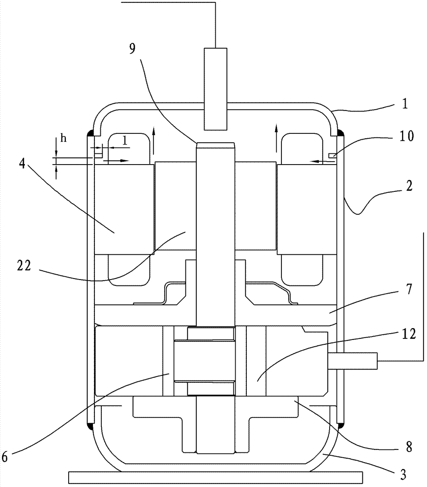
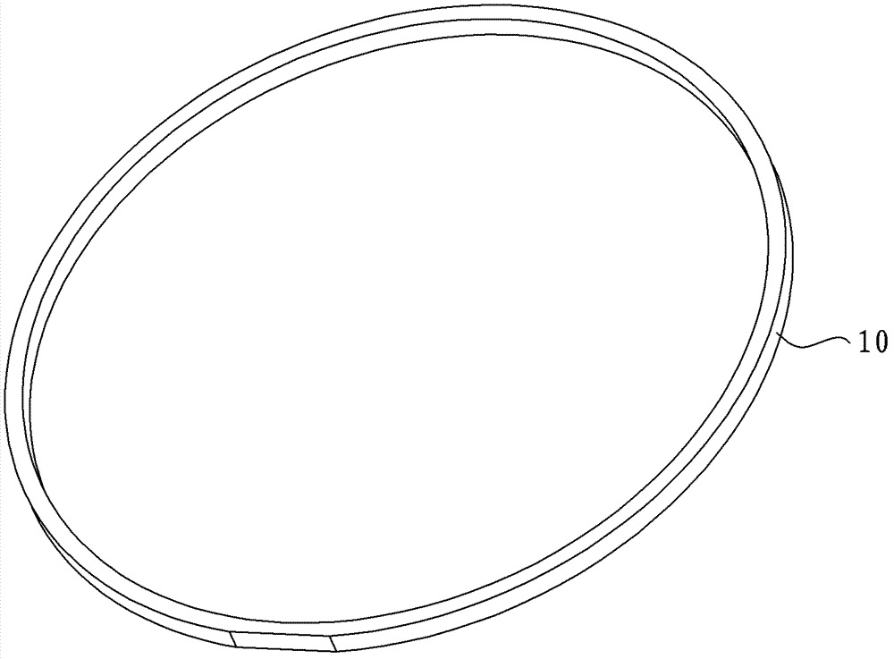
[0015] see Figure 2-Figure 8 , the oil separation device of the compressor, the compressor includes a casing surrounded by an upper casing 1, an outer casing 2, and a lower casing 3, and a stator 4 fixed in the casing, and a rotor 22 rotating inside the stator 4 And the motor assembly composed of the crankshaft 9 combined with the center of the rotor 22, and the main bearing 7 and the auxiliary bearing 8 supported on the lower part of the crankshaft 9, and the cylinder 12 between the two, which are arranged in the cylinder 12 and connected with the eccentric part of the crankshaft 9 The formed compression assembly constitutes the piston 6, and the upper end of the stator 4 in this embodiment is provided with an oil separation block 10. According to actual needs, the oil separation block 10 can also be arranged at the lower end, or the upper and lower ...


PUM


Abstract

The invention discloses an oil separating device of a compressor which comprises a casing, a motor assembly and a compression assembly. The casing is composed of an upper casing body, an outer casing body and a lower casing body in an encircling manner. The motor assembly comprises stators fixed in the casing, rotors in internal rotating connection with the stators and a crankshaft combined with the centers of the rotors. The compression assembly comprises main bearings and auxiliary bearings bearing the lower portion of the crankshaft, a cylinder disposed between the main bearings and the auxiliary bearings, and a piston disposed in the cylinder and connected with an eccentric portion of the crankshaft. One oil separating block is arranged at the upper end or the lower end of each stator, or two oil separating blocks are respectively arranged at the upper end and the lower end of each stator. Through the oil separating blocks, flow speed of gas in the compressor is reduced, flow direction of the gas is then changed to winding portions of the stators, so that oil passing by the winding portions of the stators is separated, and output of lubricating oil of the compressor is reduced. The distance h between the oil separating blocks and the stators satisfies the condition that 0< / =h< / =20S1 / pi*d. The oil separating device of the compressor improves gas circulation of the compressor, prevents the lubricating oil from forming oil film in an air-conditioning heat exchanger, improves heat exchange efficiency of an air-conditioning system, and meanwhile, improves stability of the compressor.

Description

technical field [0001] The invention relates to an oil separation device for a compressor. Background technique [0002] Lubricating oil plays the role of lubrication, cooling and sealing in the compressor. During the operation of the refrigeration system, the lubricating oil will be discharged from the discharge pipe of the compressor along with the refrigerant, and enter the condenser and evaporator, and then a layer of oil film will condense on the heat transfer wall surface of the condenser and evaporator. The coefficient is small, so that the heat exchange efficiency of the condenser and evaporator is reduced, and at the same time, the amount of lubricating oil inside the compressor is also reduced, and the internal parts of the compressor are also insufficient due to the reduction of lubricating oil. The consumption increases, which in turn leads to a decrease in compressor performance. Contents of the invention [0003] The purpose of the present invention is to p...

Claims


Application Information

Patent Timeline
Patent Type & Authority Applications(China)
IPC IPC(8): F04B39/04
Inventor 江波张河茂
Owner GUANGDONG MEIZHI COMPRESSOR
Learn More